Reinforcement design - 2D - Internal forces
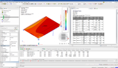
The command displays design forces, which are in the program primarily calculated as part of the Reinforcement design (ULS+SLS) procedure. However, the design forces are also applicable as standalone input for a manual design if necessary.
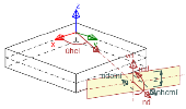
In general, the design of the 2D reinforcement meshes - prescribed at the upper/lower surface of 2D members - requires recalculation of the internal forces into the directions of the reinforcement layers (defined in the Design defaults) to enable in each direction run common uniaxial design. As a transformation procedure, the Baumann method [1] is involved with the ability to handle an arbitrary arrangement of reinforcement layers taking into account also the stiffening effect of concrete compression strut. Moreover, the shift rule can be activated in Concrete settings to incorporate into the design forces an additional tensile force in reinforcement caused by the shear. Detailed info about the whole recalculation procedure can be found in the Theoretical background.
Usage
- Calculate a FEM analysis of the model containing any 2D concrete member
- Go to Tree > Concrete > Reinforcement design > 2D members > Internal forces
- Set properties of the command to specify mainly:
- Click on [Refresh] action button to display the results
Note: To get general overview about how to work with a result services in Scia Engineer, see Results/Basics.
Properties
| Category | Property | Description / Notes |
|---|---|---|
| Selection |
Type of selection
|
Specifies on what members the results are displayed
|
| Filter
No/ Material / WildCard / Layer / Thickness |
||
| Result case |
Type of load
|
Defines for what load the results are displayed. See "Result case" |
| Extreme 2D |
Averaging of peak
|
Activates averaging of peaks of results in places where averaging strips are applied. |
|
Rib
|
Controls whether the components of internal forces parallel with the direction of the rib are neglect in area of effective width (the forces are recalculated to 1D results of the rib instead). See Results/Theory/Rib_option |
|
| Location
In centres / In nodes no avg. / In nodes avg. / In nodes avg. on macro |
Determines way how results - calculated in the nodes of individual finite elements - are further processed (averaged) to get smoother continuous distribution. |
|
|
System
|
Sets a coordination system which is used as referenced for displaying the results. See Results/Theory/Local_axes_2d |
|
|
Extreme Mesh / Member / Global |
Defines for which extreme on 2D member the results are displayed. | |
| Type of values
Design internal forces/ Design membrane forces / Basic internal forces |
Categorizes result values into the logical subgroups. |
|
| Value |
Defines what result value is graphically presented. |
|
|
Output
|
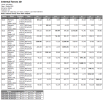
Displays numerical output with given level of detail. See the chapter Output below. |
|
| Standard result
On / Off |
Displays standard results on 2D members. | |
| Results on sections
On / Off |
Displays results on the selected sections defined on 2D members. | |
| Results on edges
On / Off |
Displays results on the edges of selected 2D members. | |
| Deformed structure
On / Off |
Displays results on deformed structure. | |
| Errors, warnings and notes settings | "Errors, warnings and notes settings" | |
| Drawing Setup 2D | Serves for adjustment of graphical output see "Drawing setup 2D" |
Values
Design internal forces
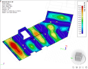
The design internal forces represent a pair of bending moment (mEd) and axial force (nEd) calculated in each direction of the reinforcement (and concrete strut) by transforming the design membrane forces from the member surfaces into the centroidal plane.
| Value | Description | Notes |
|---|---|---|
| mEd,1+ |
design bending moment in the direction of the first layer of the reinforcement mesh at upper surface |
1) The upper surface [+] of the member is always considered on the side of positive local axis z of the member while the lower surface [-] is the opposite. 2) The first layer [1] of the reinforcement mesh is always considered as the one closer to the member surface (with smaller cover), while the second layer [2] is closer to the centroidal plane of the member.
|
| mEd,2+ |
design bending moment in the direction of the second layer of the reinforcement mesh at the upper surface |
|
| mEd,c+ |
bending moment in the direction of the concrete compression strut stiffening the reinforcement mesh at the upper surface |
|
| mEd,1- |
design bending moment in the direction of the first layer of the reinforcement mesh at the lower surface |
|
| mEd,2- |
design bending moment in the direction of the second layer of the reinforcement mesh at the lower surface |
|
| mEd,c- |
bending moment in the direction of the concrete compression strut stiffening the reinforcement mesh at the lower surface |
|
| nEd,1+ |
design axial force in the direction of the first layer of the reinforcement mesh at the upper surface |
|
| nEd,2+ |
design axial force in the direction of the second layer of the reinforcement mesh at the upper surface |
|
| nEd,c+ |
axial force in the direction of the concrete compression strut stiffening the reinforcement mesh at the upper surface |
|
| nEd,1- | design axial force in the direction of the first layer of the reinforcement mesh at the lower surface | |
| nEd,2- | design axial force in the direction of the second layer of the reinforcement mesh at the lower surface | |
| nEd,c- | axial force in the direction of the concrete compression strut stiffening the reinforcement mesh at the lower surface | |
| vEd | design shear force |
Be aware, the design bending moment and axial force must always be combined when you want to perform a uniaxial design in each direction.
When a direction of reinforcement is equal for both surfaces, it’s obvious the design forces in this direction are generally the same regardless of what surface is considered. However, to emphasize only the bending moments relevant for each surface, as non-zero are generally kept the moments causing tension in the reinforcement (meaning for the upper surface mEd+ ≤ 0 while for the lower surface mEd- ≥ 0). Such approach is also valid when the design forces are presented on sections or edges of 2D members.
Design membrane forces
The design membrane forces represent direct forces in the reinforcement directions (or concrete strut) at member surfaces.
| Value | Description | Notes |
|---|---|---|
| n1+ |
design membrane force in the direction of the first reinforcement layer at the upper surface |
1) The upper surface [+] of the member is always considered on the side of positive local axis z of the member while the lower surface [-] is the opposite. 2) The first layer [1] of the reinforcement mesh is always considered as the one closer to the member surface (with smaller cover), while the second layer [2] is closer to the centroidal plane of the member. |
| n2+ | design membrane force in the direction of the second reinforcement layer at the upper surface | |
| nc+ | membrane force in the direction of the concrete compression strut at the upper surface | |
| n1- |
design membrane force in the direction of the first reinforcement layer at the lower surface |
|
| n2- | design membrane force in the direction of the second reinforcement layer at the lower surface | |
| nc- | membrane force in the direction of the concrete compression strut at the lower surface |
Basic internal forces
The basic internal forces represent the same magnitudes as in Results > 2D members > 2D internal forces.
Output
| Type of value | Graphical | Numerical | Notes |
|---|---|---|---|
| Design internal forces | 
|
|
|
| Design membrane forces | 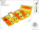 |

|
|
| Basic internal forces | 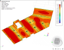
|
|

