2D Members - basic types
Definition, application
One of basic elements for modeling structures in SEN.
Where to find it
In basic tree - in group "Structure".
Overview
| 2D member | Basic description |
| Plate |
A standard plate is a planar 2D member with an arbitrary number of edges that may be straight or curved. |
| "Definition of a composite deck" |
A deck (composite deck or metal deck) is essentially a plate in SCIA Engineer. It may be input as any 2D member that accepts ribs. That includes plates and straight walls. To define a composite deck, the user would usually define a standard plate, or a ribbed plate in the case that he would like to assign the ribs in the very same modelling operation. A composite deck is created from a standard plate via the property Element type. This property defines whether the 2D member is a standard plate, a composite deck, or a metal deck. |
| Metal deck | |
| Ribbed Slab |
2D slab member with possibility to define ribs from Cross section library. |
| Prefab slab | |
| Wall |
A wall is a vertical 2D member whose base is either straight or curved |
| Masonry Wall | A wall is a vertical 2D member whose base is either straight or curved from material "Masonry" and orthotropic behaviour. |
| Shell |
Shells are defined by border lines (i.e. border curves). The shape of the shell can be defined by four, three or two curves / straight lines. Some shapes require certain "mathematical imagination" when they are created. Therefore, the basic shapes has been pre-created in the form of templates and can be easily input through user blocks. |
| Shell - surface of revolution | |
| Shell - swept surface |
Slab parameters
Name
Defines the name of the slab.
Element type
Standard = standard finite element plate
Metal deck = special type intended for decks made of a profiled steel sheeting
Composite deck = special type intended for decks made of a profiled steel sheeting with a concrete topping
Load panel = allows to switch the 2D member to a load panel
Masonry orthotropic = it is used for masonry walls and automatically define orthotropic behaviour of wall.
The options Metal deck and Composite deck are available only when both concrete and steel materials are enabled in the project settings; see details in the chapter Composite Analysis Model
The option Load panel is available only in the post-processing environment v17; when switching to Load panel type, a number of additional settings are available, related to the load panel functionality
Element behaviour
Standard FEM = standard finite element plate in the analysis model
Flexible diaphragm = only axial in-plane stiffness, no bending stiffness; load transfer ensured by built-in load panel functionality
Semi-rigid diaphragm = in-plane stiffness identical to Standard FEM, no bending stiffness; load transfer ensured by built-in load panel functionality
Rigid diaphragm = infinite in-plane stiffness, no bending stiffness; load transfer ensured by built-in load panel functionality
Diaphragm behaviours are available only for Metal decks and Composite decks; see details in the chapter Composite Analysis Model and also more information about 2D Member Element Types & Behaviours
Type
Specifies the type of the slab. The user may select from types: (i) plate, (ii) wall, and (iii) shell.
This type plays role e.g. in code checks. The check procedure applied depends on this parameter. Therefore, pay attention to the selection of proper type.
Material
Defines the material of the slab.
FEM model
Isotropic = A normal isotropic slab with identical properties in all directions is used.
Orthotropic = An orthotropic slab with different properties in two orthogonal directions is used.
Membrane = Special membrane elements are used for the analysis of the slab.
Press only = Special elements capable of resisting only compression stress are used for the analysis of the slab.
Thickness type
It is possible to input a slab of constant or variable thickness.
See also paragraph Variable thickness later in this chapter.
Thickness
For constant thickness, just one thickness value must be defined.
For variable thickness, two thickness values must be defined. Input of slabs with variable thickness is described in a separate paragraph below. Also the relevant parameters are described in that section.
Orthotropy (for orthotropic FEM model only)
This item specifies the orthotropy type of the slab. It also enables the user to open the Orthotropy manager and define a new orthotropy type.
Member system-plane at (not for membrane FEM model)
The input-plane (system-plane) of the input slab may be in the mid-surface of the slab, at the top surface or bottom surface of the slab.
Eccentricity z
If required, eccentricity of the slab may be input.
LCS type
Defines the type of the local coordinate system of the slab.
See also paragraph LCS types later in this chapter.
The orientation of the local Z axis of the slab may be easily turned around. This check box does it. See paragraph The effect of the Swap orientation parameter later in this chapter.
LCS angle
The direction of the local X-axis may be input here.
Layer
Selects the layer of the slab. It also enables the user to open the Manager of layers and define a new one.
Geometry parameters for walls
Height
Defines the height of the wall.
Insertion point
Specifies whether the bottom base or the top base of the wall is input.
Variable thickness
The variable thickness of a slab can be input in the property table of a slab. There are several options to choose from.
Direction X
The thickness varies in the global X-direction.
For this option the user can select two points in which the thickness is specified. Then the user can input the two thickness values for the two points.
Note: Attention must be paid to the selection of the two points. If two points located on a line parallel e.g. to the global Y axis, nothing happens - the variable thickness in the global X-direction cannot be calculated for such input.
Direction Y
The thickness varies in the global Y-direction.
For this option the user can select two points in which the thickness is specified. Then the user can input the two thickness values for the two points.
Read also the for the Direction X above.
Direction Z
The thickness varies in the global Z-direction
For this option the user can select two points in which the thickness is specified. Then the user can input the two thickness values for the two points..
Local X
The thickness varies in the direction of the local x-axis of the slab.
For this option the user can select two points in which the thickness is specified. Then the user can input the two thickness values for the two points.
The local x-axis is normally defined by the first two input vertices of the slab.
This option is not available for slabs input as shells (i.e. using function 2D member > Shell)!
Local Y
The thickness varies in the direction of the local y-axis of the slab.
For this option the user can select two points in which the thickness is specified. Then the user can input the two thickness values for the two points.
This option is not available for slabs input as shells (i.e. using function 2D member > Shell)!
Variable in two directions
The user selects three points (slab vertices) in which the thickness will be specified. Then the user can input the three thickness values for the three points.
This option is not available for slabs input as shells (i.e. using function 2D member > Shell)!
Variable in 4 points
This option is available only for slabs with four vertices.
The user selects four points (slab vertices) in which the thickness will be specified. Then the user can input the four thickness values for the four points.
Radial
This option is available only for circular slabs.
The user defines the thickness in the centre of the slab and on its edge.
It is advisable to input the points in place where the thickness change starts and ends. Otherwise it may happen that due to the extrapolation of thickness, the final thickness value becomes negative, which would result in an error message during the calculation of the project.
The definition of a slab of variable thickness is a two-step procedure. First, a slab of a constant thickness must be input. This slab may be then modified and changed into a slab of variable thickness. The reason is that the "property" of variable thickness is bound to the particular nodes of the slab that are not yet known in the phase of slab input. In other words, variable thickness is similar to a haunch on a 1D member – it is an additional property of a slab, not the basic, fundamental parameter.
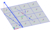
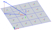
Local coordination system for 2D member and mesh elements
The results of a Finite Element analysis are primary computed with respect to a Local Coordinate System (LCS) of mesh elements inside the 2D member. As a consequence, these results - among others like a generated load or designed reinforcement - depend on the way the local axes for mesh elements (and 2D member respectively) are defined.
Warning: Be aware, the LCS of mesh elements and 2D member itself may vary depending on the selected method for LCS definition. Such discrepancy is important to notice mainly in Results service, because both systems (LCS - 2D member / LCS mesh element) can be used as referenced for the presentation of the results.
A wrong definition / selection of local axes system can lead to very misleading results so it's always recommended to check the orientation of the considered local axes system graphically. To visualize local axes of mesh elements or 2D member you can use the View parameters settings (for the mesh local axes, first the mesh itself must be generated).
The change of LCS system of the 2D member can be done using the following properties:


