Automatic calculation of the effective width of plate ribs - assumptions & limitations
Assumptions and limitations
Consistency of the calculation
Within a continuous beam, all members must use the same calculation method of the effective width. It is not allowed to mix in a continuous beam members that use the EN 1992 and EN 1994 methods.
However, it is possible to combine automatic calculation of effective width according to any supported method with manual input of effective width. This is useful, in case the geometry of the structure does not comply with the pre-requisites of the provided methods and must therefore be adjusted manually. In such a case, it is possible to adjust manually the effective width of some members in a continuous beam while other members are processed automatically.
Uniform effective width per member
The effective width is calculated as a uniform value per member. That assumption corresponds to the mentioned design codes.
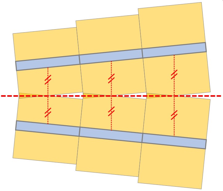
It is however possible, in the case of nearly parallel beams, to take into account the variable spacing of the beams by splitting each span into several members (see below, detection and distance to adjacent beams and edges).
A 1D member may not cover more than one span for the automatic calculation of effective width. If it does, the calculation of effective width will fail and the rib will switch back to manual input. Continuous beams should therefore be modelled as multiple 1D members, rigidly connected to each other.
Effective width for internal forces and for check
For the EN 1992 method (concrete beams), the effective width value for internal forces is calculated per member, according to the method described in the code. By default, the value for check is taken equal to the value for internal forces. It can, however, be overwritten manually with different values (see "Automatic calculation of the effective width of plate ribs - settings in SCIA Engineer").
For the EN 1994 method (composite beams), the effective width value for internal forces is calculated per member, according to the method described in the code. The value for check is not displayed in the properties of plate ribs, as the effective width for checks is computed separately during the check according to a more detailed method (also described in EN 1994-1-1). For more information, see "Composite Checks")
Unsupported cases
The current implementation supports only the methods described here. For special, unsupported use cases, it is recommended to use manual input of the effective width.
Selection of the calculation method
When automatic calculation of effective width is selected for a plate rib (property shape of rib = automatic), the calculation method is selected according to the primary material of the cross-section of the beam.
- If the material is concrete, the EN 1992 method is used.
- If the material is steel, the beam is assumed to be composite and the EN 1994 method is used (or AISC 360-10 for IBC projects).
- For all other materials, the method is defined by the corresponding setting in the solver setup. The default method is EN 1994.
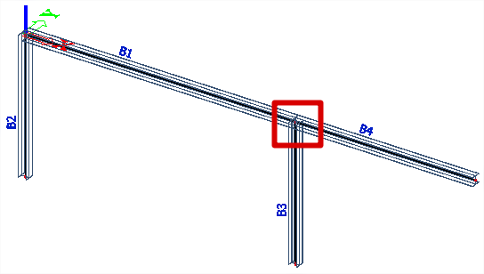
Detection of continuous beams and supporting system
The span length does not necessarily correspond to the length of the considered 1D member. A span may be composed of several beams.
A span is defined according to the information that can be found in the System lengths and buckling settings of each beam, in the direction perpendicular to the plane of the slab the considered beam is attached to.
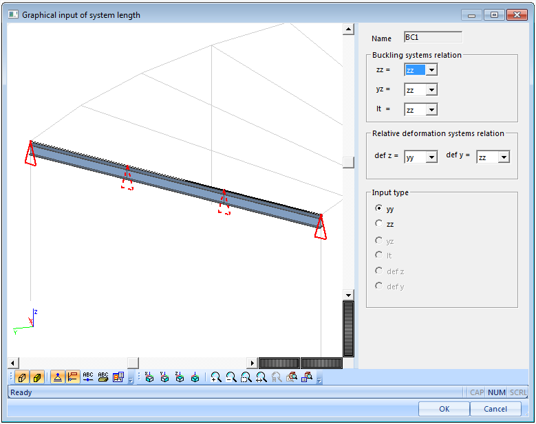
In the example above, the span is composed of 3 beams. The span is simply supported. Two possible boundary conditions at 1/3 and 2/3 of the span are disabled, because there is no support nor supporting column in those points.
Important: effective width is calculated as a uniform value for each span. Distinct spans usually have different effective width values. As SCIA Engineer supports only uniform effective width on a beam, it is not allowed for a beam member to exceed one span. Therefore, any inner support or supporting member along a beam will be ignored during the automatic calculation of effective width. Only supports and supporting members located at an end of a beam will be taken into account.
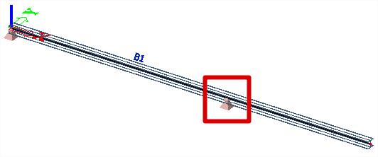
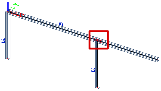
Always split members at supports, in order to obtain correct calculation of the effective width. The examples here are not OK: there is either an inner support on the beam, or a column connected to the beam via an inner node. One can see, that the beam is made of one member covering two spans. Those boundary conditions will be ignored by the automatic calculation of effective width.
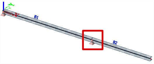
The beam should be split in two members, as shown in the following examples. The boundary conditions are then applied to beam end nodes and will be taken into account correctly.
Additionally, please note, that boundary conditions for the calculation of effective width may be modified manually via the System lengths and buckling settings of the members.
Detection and distance to adjacent beams and edges
When determining the available distance on each side of a beam, SCIA Engineer detects entities that are parallel to the considered beam.
Only entities that fulfil all the following conditions are taken into account. Those are plate ribs, outer edges or opening edges that are:
- parallel or nearly parallel to the considered beam; a tolerance angle is configurable in the solver setup (default=10°)
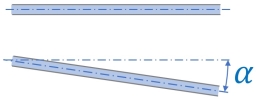
- linked to or contained by a plate that is
- located in the same plane as the slab that contains the considered beam
- connected by at least one edge to the containing slab of the considered beam (a single point connection is not sufficient)

The distance to the adjacent entity is calculated at mid-length of each member.
It is however possible, in the case of nearly parallel beams, to take into account the variable spacing of the beams by splitting each span into several members.
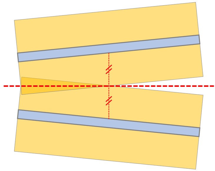
Similarly, a span may be split into several members in case there is an opening next to it, thus constraining its effective width on part of its length.
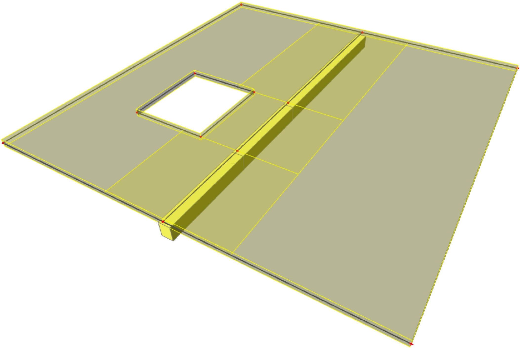
Determination of the contact width
For the EN 1992 method, the width of the contact surface between the rib and the plate is used as part of the effective width.
The contact width value is determined from the distance between the outermost points of contact between the cross-section of the rib and the plate.
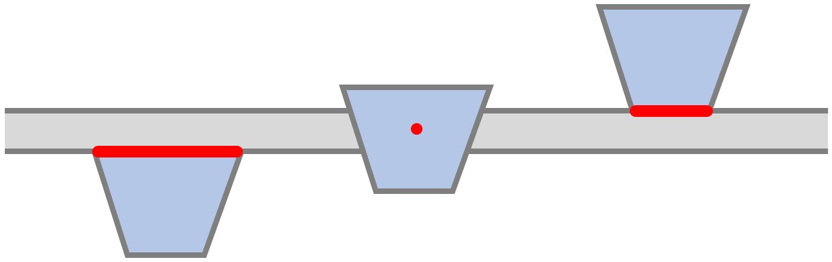
The face of the cross-section that is considered depends on the placement of the beam relative to the plate (see figure above). If the Alignment property the beam is:
- Bottom, then the upper face of the cross-section is considered
- Centre, then the contact width is taken as zero; please note, that this is a case where the formulas from the Eurocode to not apply, as the resulting cross-section cannot be considered as a T-section.
- Top, then the lower face of the cross-section is considered
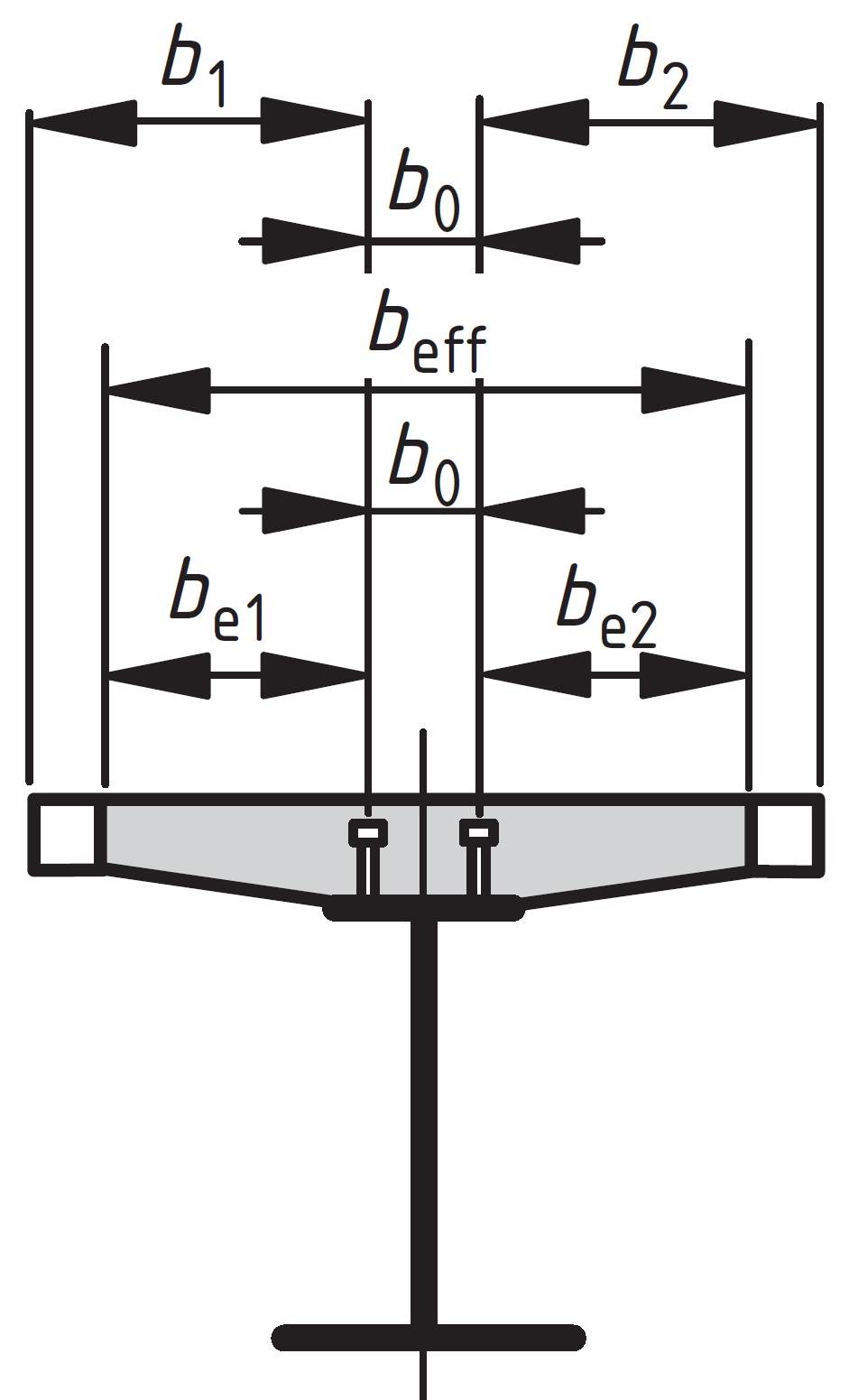
For the EN 1994 method, there is no contact width per se, as that parameter is replaced by the transverse distance b0 between the rows of shear connectors (see figure above). In SCIA Engineer, the algorithm conservatively assumes that there is a single of row of connectors, therefore using a contact width equal to zero.