System lengths and buckling settings
Since SCIA Engineer 18.0 a new dialog is introduced for applying buckling settings on a specific buckling system called System lengths and buckling settings. Prior to SCIA Engineer 18.0 there was a dialog for the buckling settings called "buckling and relative lengths" which offered similar settings but without the graphical window and even without the results.
The new dialog is an improvement of buckling and relative lengths in order to offer the user a better user interface and also a better user experience. The settings have been grouped in a more logical order so that the user can navigate seamlessly within the dialog.
System lengths and buckling settings can be accessed either:
- via Libraries > Structure, analysis > System lengths and buckling groups > click on new for creating a new buckling group or click on edit to modify an existing buckling group.
- via 1D-member property > System lengths and buckling settings.
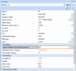
The buckling related settings that are configured in System lengths and buckling settings are saved into a buckling group (BG) which is listed in the "System lengths and buckling groups" dialog and also when assigned it can be seen in the 1D-member properties as shown in the example below:
Dialog arrangement
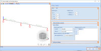
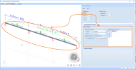
The picture bellow displays the dialog of System lengths and buckling settings:
First tab:
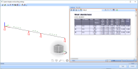
Second tab:
The different sections of the dialog are numbered and explained below in detail.
1) Graphical window of the buckling system
The left part of the dialog gives the user a graphical representation of the 1D-members in the buckling system with their buckling constraints and information about the sway settings per span. It is not only a representation of the above mentioned settings but it also allows editing directly in that graphical window by clicking on the buckling constraints to set them to fixed/free or by clicking on the sway symbols per span to set them to yes/no/acc. to material setup.
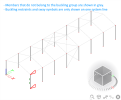
Members that belong to the buckling system are visualized with a black line while the other members within the project are greyed out. This gives the user an overview on which members are using that specific buckling group. Also the buckling constraints symbols (red triangles or rectangles) and the sway symbols are only visualized on 1 system line (first system line if the dialog is accessed from System lengths and buckling groups or the system line of the current selection if it is accessed from the 1D-member property System lengths and buckling settings), see the example below.
Used symbols
For the buckling constraints there are two symbol types depending on the chosen span:
- Triangle symbol (buckling span y-y, z-z and also for the deflection span deflection y, deflection z)
- Rectangular symbol (buckling span y-z, LTB)
A solid line for both symbols represents the fixed state (i.e. active restraint) and a dashed line represents the free state (i.e. inactive restraint).
For the sway settings there are three symbol types depending on the chosen sway setting:
- Dashed line (sway settings according to the project defaults defined in the material setup)
- Solid line with a cross (Sway = No, symbol for non-sway)
- Solid line with the arrows (Sway = Yes, symbol for sway)
Icons in the graphical window
In the graphical window the following icons can be found:
1) Show/hide surfaces
2) Render geometry
3) Show/hide supports
4) Show/hide other model data
5) Show/hide node labels
6) Show/hide member labels
7) View parameter settings
8) Clipping box on/off & Clipping box settings
Sending snapshot to the Engineering Report
A useful feature is the possibility to send the 3D-scene of the dialog as a snapshot to the Engineering Report. This helps in visualizing the used buckling constraints and sway settings in the Engineering Report. Sending a snapshot to the Engineering Report can be done by right mouse clicking in the graphical dialog > Screenshot into Engineering Report
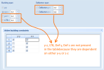
2) Buckling and Deflection span
The buckling settings are visualized within the dialog based on the selected buckling span or deflection span. It defines the context of the settings that are visualized. For example when the y-y span setting is selected the graphical window shows the buckling constraints for y-y as well as the sway settings for y-y. Also the span settings group shows the settings in the y-y context.
System relation
Behind every buckling span (excluding y-y) and deflection span there is a combo box that defines the system relation. The system relation is in fact defining whether a buckling span or deflection span is using the same constraints (triangles/rectangles) of another buckling span or deflection span. In essence you can make the buckling span or deflection span dependent on another one by selecting another span other than itself or you can make it independent from the rest by selecting the same span.
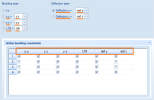
3) Active buckling constraints
The Active buckling constraints table allows the user to modify the buckling or deflection constraints in a tabular form. An alternative would be to do it per buckling span (y-y, z-z,...) in the graphical window by clicking on the red restraint symbols (triangles/rectangles). The downside of this method is as indicated that you can only do it one buckling span at a time.
An overview of all active buckling constraints are presented in the table. Notice in the picture below which represents the default setting that y-z, LTB, def y an def z are not available because they are dependent on either y-y or z-z.
Only independent buckling spans or deflection spans are visualized in the table. Making them independent can be done by setting the buckling span or deflection span equal to itself. Below an example in which all buckling spans and deflection spans are made independent of each other:
Productivity booster: copy/paste to and from Excel
All tables within the dialog support copy/paste to and from Excel. This enables the user to execute certain manipulations in Excel and afterwards paste it back into the table. For instance the user can copy the content of the Active buckling constraints table by right mouse clicking on one of the row numbers > Copy all
Next it can be pasted into Excel in which the user can modify multiple cells at once and once finalized it can be copied from Excel.
And finally pasted back into SCIA Engineer by right mouse clicking on one of the row numbers > Paste all
4) Span settings
Under the span settings group you can find all the buckling settings related to the spans. The span (y-y, z-z, y-z, LTB) settings that are shown under span settings depends on the selection under buckling span in the top section of the dialog.
Below you can find an overview of the different span settings depending on the chosen buckling span in the top section of the dialog.
Buckling span y-y and buckling span z-z
| Span setting | Steel, other - Timber - Aluminium | Concrete |
|
ky factor or kz factor
|
- Calculate: buckling factors are calculated (see - Factor: buckling factors are manually inputted by the user. - Length: buckling lengths are manually inputted by the user. |
- Calculate: buckling factors are calculated (see - Factor: buckling factors are manually inputted by the user. - Length: buckling lengths are manually inputted by the user. - Support: Supports (fixed, hinge, free, roll) are manually inputted by the user per span. Based on the inputted supports a buckling factor is obtained. - Code dependent: buckling factors are calculated via a code dependent method (only available for IBC-code). |
| Sway y-y or Sway z-z |
- From setup: Uses the sway settings coming from the material setup - All sway: sets all spans of the axis system as sway - All non-sway: sets all spans of the axis system as non-sway - Custom: allows editing the sway settings per span |
- From setup: Uses the sway settings coming from the material setup - All sway: sets all spans of the axis system as sway - All non-sway: sets all spans of the axis system as non-sway - Custom: allows editing the sway settings per span |
| Member imperfection in 2nd order analysis |
Bow imperfection e0,y or e0,z: - Acc. to code (EN 1995) - Acc. to code (EN1993/EN1999) - elastic: usage of bow imperfections as defined in the code for elastic analysis - Acc. to code (EN1993/EN1999) - plastic: usage of bow imperfections as defined in the code for plastic analysis - Acc. to code (EN1993/EN1999) - elastic - if required: usage of bow imperfections if required as defined in the code for elastic analysis - Acc. to code (EN1993/EN1999) - plastic - if required: usage of bow imperfections if required as defined in the code for plastic analysis - Manual input of bow imperfection - No bow imperfection |
Total height determination: - Calculate: the total height is calculated automatically as the sum of lengths of all members in that buckling system. - Input: the total height is inputted manually
my or mz: my : is the number of vertical members contributing to the total effect of the imperfection perpendicular to the y-axis (LCS). That value is used for the recalculation of the bending moment around the y-axis. mz: is the number of vertical members contributing to the total effect of the imperfection perpendicular to the z-axis (LCS). That value is used for the recalculation of the bending moment around the z-axis. |
Settings per span for y-y axis and z-z axis
Under settings per span for y-y axis and z-z axis the user can input the settings per span.
| Table column header (Steel - Timber - Aluminium) | Table column header (Concrete) |
| ky or kz: allows manual input of the buckling factor per span | Beta yy or Beta zz: allows manual input of the buckling factor per span |
| ly or lz: allows manual input of the buckling length per span | ly or lz: allows manual input of the buckling length per span |
| Sway y-y or sway z-z: allows manual input of the sway settings per span if the combo box for sway is set to custom. Otherwise it displays the sway settings coming from the combo box (from setup, all sway, all non-sway) | Sway y-y or sway z-z: allows manual input of the sway settings per span if the combo box for sway is set to custom. Otherwise it displays the sway settings coming from the combo box (from setup, all sway, all non-sway) |
| Top y-y/z-z and bottom y-y/z-z: allows manual input of the boundary supports of each span. |
Buckling span y-z
The span settings when using the buckling span y-z allows the user to input the kyz factor per span (not available for concrete).
Buckling span LTB
The span settings when using the buckling span LTB allows the user to input the following factors per span (not available for concrete):
- kltb: allows input of the LTB-factor which is multiplied with the system length in order to obtain the LTB-length
- Mcr: allows input of the elastic critical moment Mcr
- k: factor related to end fixity
- kw: factor related to warping end fixity
5) Advanced settings
Lateral Torsional Buckling
Settings related to lateral torsional buckling can be found under this group:
- Point of load application: The position on which the load will be applied on the 1D-member (on top, in shear center, on bottom, always destabilising, always stabilising). This setting influences the Mcr calculation for the LTB check.
- Mcr: this setting can be set to calculate in order to calculate it or input to input it manually under the span settings when using the buckling span LTB.
Warping check
When activating the tick box warping the user can define the end constraint conditions for warping. More information regarding the warping check can be found here: "Annex F: Warping check"
Special buckling systems
Special buckling systems (only available for steel) are intended for lattice tower members but can be applied on either member if desired. More information can be found here: "Calculation buckling ratio for lattice tower members" and "Calculation buckling ratios for crossing diagonals"
6) Save or Cancel
These two buttons offer the user to either:
- Save the applied modifications in the dialog
- Cancel the applied modifications in the dialog
7) Results
The results tab is available if both conditions are fulfilled:
- The buckling group is assigned to a member or a group of members
- The project is calculated (linear calculation)
The results tab displays the slenderness data which can also be found in every material service menu. The benefit of this results tab is that the user can see the slenderness data only for the members that are using that buckling group. In essence the user does not need to leave the dialog because the settings are located in the first tab and the dependent results are located in the second tab.
The results table can be sent to the Engineering report if needed by using the designated icon located at the top section.

