Plane section entity
Introduction
Plane section entity (PSE) is a separate object in SCIA Engineer. It enables the user to create a 2D projection of the structure. This projection together with dimension lines and labels will be used as a drawing.
PSEs have their own properties and can be manipulated using standard geometrical manipulations. View parameters are not available in Drawing view, displaying of drawings is controlled by drawing rules.
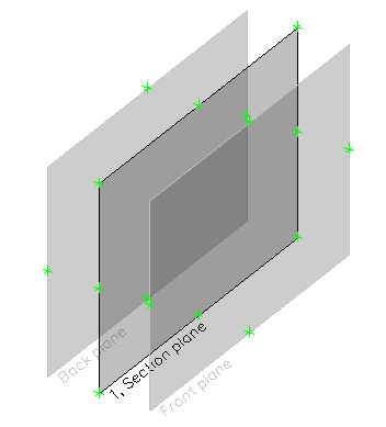
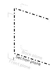
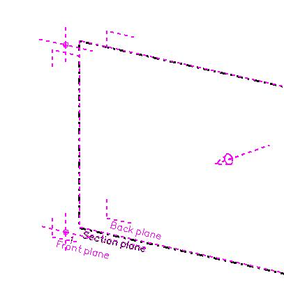
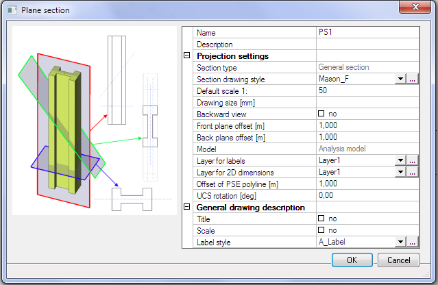
The PSE consists of 4 basic planes. The meaning of those planes is:
1. Geometry plane (labelled by “1” on the picture) is the real geometry created by the user. Vertexes of this plane are used for modifications of PSE shape.
2. Section plane: in this plane the 2D projection of the structure is drawn
3. Front plane: is the front limit of the structure. Structure further from the section plane will not be projected.
4. Back plane: is the back limit of the structure. Structure further from the section plane will not be projected.
The geometry of PSE is a planar polygon and it represents the geometry plane. Positions of other planes are defined in properties of PSE.
The arrow for the selected PSE shows the user’s view direction. The view direction is from the back plane to the front plane. This direction is derived from process of inserting the Plane section.
Types of Plane section entity
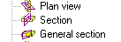
There are three basic types of PSE differentiated according to its
intended usage:
1. Plan view: created as a polygon in the current work-plane (similarly as a slab is created).
2. Section: user specifies the line and the top and bottom. The section is created according to properties from inserted command (similarly to a wall input). The section is always created as a plane perpendicular to the XY plane of the current UCS.
3. General section: created in the same way as a plan view but this type has identical geometry plane and section plane.
Geometry
of all types of PSE is always a polygon and can be changed any
time later - individual vertex points can be moved.
Plan
view can be inserted also in XZ or YZ type of work-plane.
Geometry
can be changed also by Table edit geometry.
Drawing
view generates a drawing from the 3D analysis model, the only
exception is 1D members like plate rib.
Creating new PSE
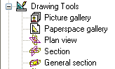
Inputting commands for PSE are accessible from main group “Drawing tools”. Three basic types are available.
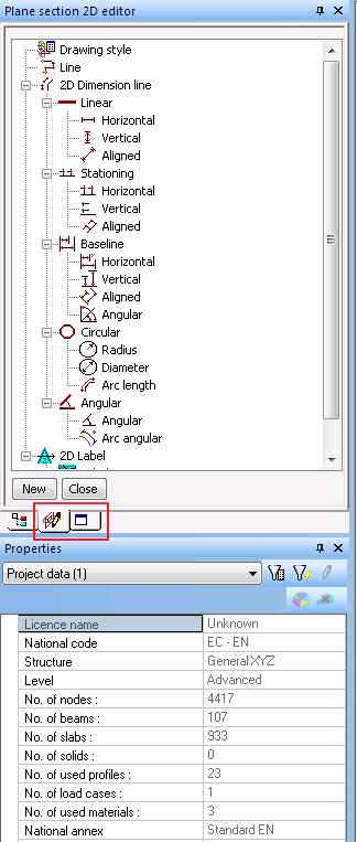
When the user creates a PSE then the application opens tree menu called 2D editor. If, together with the 2D editor tree menu, also the Structure service is opened, the Drawing view has no properties to prevent deleting PSE in 3D model.
New PSE – Plan view
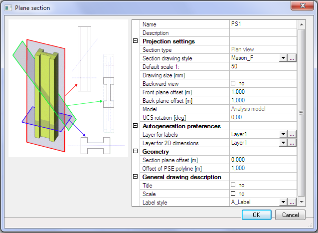
The plane section dialogue with properties is displayed as the first step in creating each PSE. The plan view is defined by a polygon graphically inserted to the working plane. Each PSE has its default Drawing style in the properties. The Refresh button for generation of the drawing is displayed as an action button in the properties of already created Plane section.
New PSE – Section
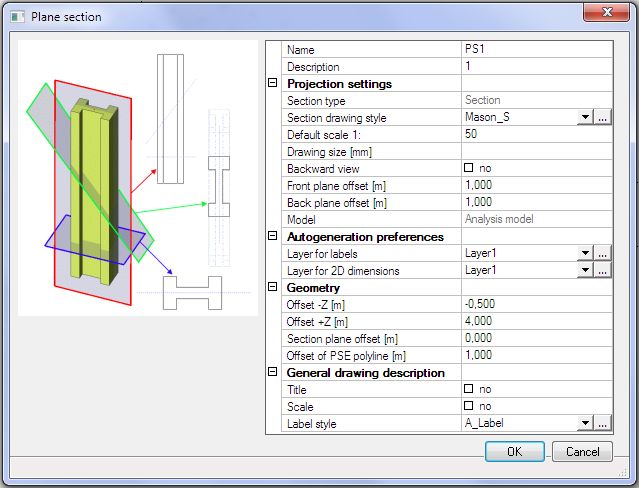
The Property dialogue for insertion of a Section is similar to the property dialogue for Plan view, but the geometry is limited in the Z direction by offset –Z and +Z (The same definition as for a wall).
New PSE – General section
Input of a General section is similar to the input of the Plan view. Only the Section plane offset property is missing.
Properties of plane section
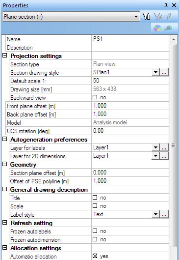
- Name: standard property for all entities in SCIA Engineer
- Description: the “real” name of the section (plan view). It can be changed in the property dialogue. Only type Section fills in the Description automatically by a number.
The description is automatically numbered for copied or newly created sections.
- Section type: information about section type. See separate chapter
- Section drawing style: list of available drawing styles. The selected drawing style is used for creation of the projection. See separate chapter.
- Default scale: the scale which is assigned to a picture when it is placed on the paperspace or when it is placed to the picture gallery. Displaying of projection in Drawing view is based on this scale (see separate chapter). This scale is compared with “Intended scale” (see Drawing style) and when it does not match a warning message is displayed.
The scale in the picture gallery is automatically generated only during insertion of the picture. Further changes of scale will not affect the Drawing view.
- Drawing size: the size of the drawings in selected units (settings are in Setup>Units>Geometry>Length-drawing), it is calculated according to the scale of the PSE.
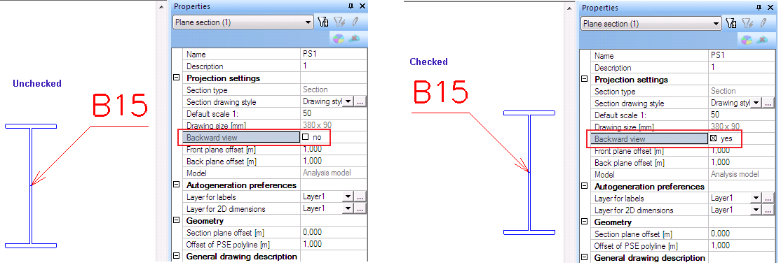
- Backward
view: mirrors the whole Drawing view scene – generated structure,
autolabels and autodimensions
- Front plane offset (m): the distance between “Section plane” and “Front plane”, only positive values are accepted
- Back plane offset (m): the distance between “Section plane” and “Back plane” ”, only positive values are accepted
Geometry of Front and Back plane can be changed by function “modify vertexes”.
- Model: the user can select which model will be used for generation of the projection. The structural model can be selected only when the Structural model functionality is checked. In this case all Autolabels are generated to the centreline of the Structural model (not Analysis model) and the projection is generated according to the structural model.
- UCS rotation: the angle of UCS of appropriate PSE
- Layer for labels: The layer for all labels created in the Drawing view
- Layer for 2D dimensions: The layer for all 2D dimension lines created in the Drawing view
Layers can be changed either during the definition of PSE or later.
- Section plane offset: the distance between “Geometry plane” and “Section plane”
- Offset of PSE polyline: the function for enlargement of the PSE geometry, only positive values and zero are accepted, this offset is applied to all the sides of the PSE polyline
- Title and Scale: Places autolabels to the drawing, Title is generated from the “Description” and Scale from “Default scale 1:...”
The visibility of Title and Scale is handled by checkboxes. When a particular label is moved, it keeps its position during unmarking and marking of the checkbox. Action button Reset modifies their position to the default. The change of Label style affects Title and Scale immediately.
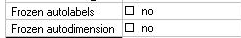
- Frozen autolabels: checking of this checkbox disables any changes for autolabels – it is frozen for refresh and reset action button
- Frozen autodimensions: checking of this checkbox disable any changes done for autodimensions – it is frozen for refresh and reset action button
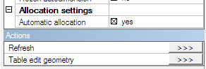
- Allocation settings: the list of entities which will be projected on the Section plane
- Automatic allocation: all entities between the front plane and back plane are included to Filtered allocation. Other entities are removed from the allocation
- Manual allocation: list with available and selected entities for allocation
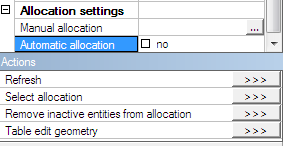
Automatic allocation: allocates automatically all entities included in PSE, i.e. between the front and back plane of PSE, by default it is checked. When it is unchecked – Manual allocation is possible and new action buttons appear.
Manual allocation: the user can choose entities in allocation using graphic selection (by Select allocation action button) or from a list.
The projection is created from all entities included in the Filtered allocation. It is independent on activity settings.
Action buttons:
- Refresh: recreates the projection of the structure on the Section plane, refreshes autolabels and autodimensions according to the rules. It can be used for multirefresh (for more selected PSE in 3D model).
To see the projection in 3D window, relevant view parameter must be switched ON (see chapter about the Drawing view)
- Reset: erases autolabels and autodimensions, also their position is changed to the default if they are not frozen
- Select allocation: graphical selection of allocated entities
- Remove inactive entities from allocation: entities currently inactive are removed from the Filtered allocation
- Table edit geometry: standard tool for manual editing of a polygon (PSE geometry) shape
Change of PSE geometry using “Move vertexes” function
Moving of corner vertexes on Geometry plane influences the shape of PSE polygon itself.
Corner vertexes can be moved only in the plane of the Plane Section Entity.
Moving of vertexes in the middle of edges influences the value in the properties describing the position of the planes (see description of the properties). The inner vertexes can be moved only perpendicularly to the plane of the Plane Section Entity.