New command for design reinforcement
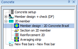
Design of longitudinal reinforcement runs from the completely new command Member design – 2D Concrete Brazil in the tree Concrete > 2D member .
Command properties
The command design of longitudinal reinforcement includes standard attributes and parameters where it is possible to select member, type of load, filter, extreme and others. The description of all values is the following.
Name
User is allowed to name this command. It might be very useful for better specification and orientation, especially in document. Default name is 2D Concrete Brazil.
Type of loads
By this attribute user defines the type of the load for design. There are three possibilities to choose from:
Combinations
user may choose from all combinations
Load cases
user may choose from all load cases
Class
user may choose from all result classes
In dependence on selected type of the load, new attribute Combination or Load cases or Class will appear right under this attribute. User may select desired Combination. Load case or Class from filtered list here.
This parameters are in group Result case
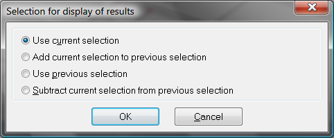
Type of selection
This attribute influences the total amount of members, which will be taken into account for calculation. There are four possibilities to be chosen from:
All
all active 2D members will be taken into account for design
Current
only selected 2D members will be taken into account for design
Advanced
user may define the selection more specifically with relation to previous selection
Named selection
only 2D members from certain named selection, will be taken into account for design. New attribute Named selection will appear in the command.
Filter
It is possible to define filter for adjusting already selected type of selection. This will affect the number of 2D members taken into account. User may select one from the following possibilities:
No
no filter will be applied
Wildcard
user may define the attributes for selection by himself
Thickness
user may select thickness of the 2D member
Material
user may select specific material
Layer
Again, after selection one possibility a new appropriate attribute will be displayed right under, for further selection.
Parameters Type of selection and filters are in a group Selection
Location
This parameter defines the location, where the design will be calculated. This is based on FEM results. If user changes this attribute, then SCIA Engineer needs to make internal calculation of design forces. User may choose from four possibilities:
In centres
(results represented in centre of gravity of each element, the design value for design is calculated directly from no avg. values by arithmetic average)
In nodes, no avg.
(results represented in mesh nodes, for each element separately, these are the main results which are base for all other design location possibilities)
In nodes, avg.,
(results represented in mesh nodes, but on the opposite of no avg. values, all values from all adjacent 2D members in each node are recalculated by SCIA Engineer before design and only one value for each node will be represented)
In nodes, avg. on macro
(the same as In nodes, avg. possibility with one important difference. the recalculation is done only on each 2D member separately, this means that one 2D member will not be influenced by another 2D member, also note that there might be more same values)
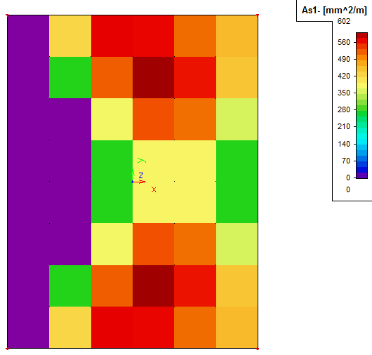
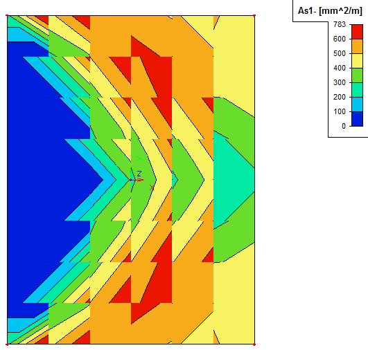
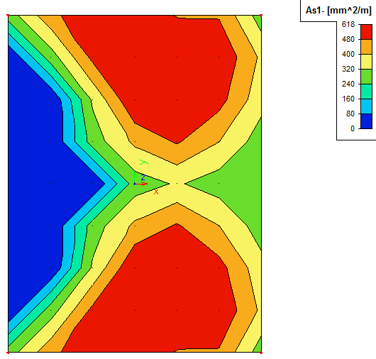
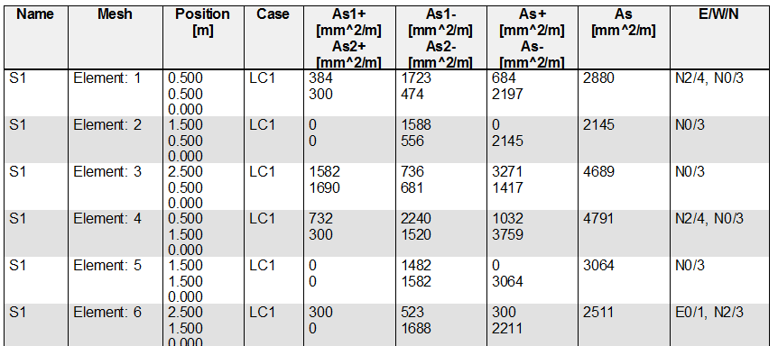
We can show the differences of the designs for example on required reinforcement amount (As1-) calculated on example.
|
In centres |
In nodes, no avg. |
|
|
|
|
In nodes, avg. |
In nodes, avg. on macro |
|
|
|
System
This attribute defines used coordinate system. It is not possible to adjust this attribute. It is set to Local, it follows that direction of reinforcement defines in Concrete setup is related to x axis of LCS of 2D mesh element.
Each element of 2D member can have different LCS. It can be set in properties of 2D member (LCS Type)
Output
This attribute defines type of numerical output. There are available two levels of numerical outputs:
Brief
one table for all type of outputs
Standard
one table for each group of result.
Extreme
This attribute defines which results should be shown in Preview window or Document. User may choose from three possibilities:
No
(results for all elements will be displayed on selected 2D members)
Member
(only elements with maximum results on each of selected 2D member will be displayed)
Global
(only elements with maximum results on selected 2D members will be displayed)
Print symbol explanation
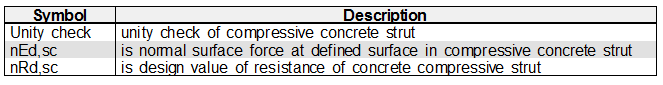
If this attribute is active, then symbols used in tables of numerical output are explained in additional table. Table consists of three columns (symbol, description and reference if it is relevant).
Print E/W/N explanation
If this attribute is active, then E/W/N (E – errors, W – warnings and N – notes) marked with appropriate numbers will be displayed in the numerical window when some E/W/N appears. More information about the error may be found in chapter "New system of warnings and errors".
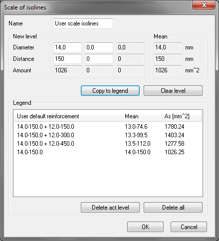
Use user scale isolines
This feature enables the user to define own scale which will affect the view of the graphical results. Simply said, user may define his own key points on the scale. This might be very helpful for better orientation in used types and amounts of reinforcement. By switching this attribute on, another attribute User scale isolines will appear right and user may define his scale through dialog shown below:
Where buttons:
When this User scale will be used, then the scale in the top right corner of the graphical window will look like this:
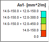
User may also use possibility to draw isolines together with labels. Together with export of the slab picture it might be very useful to transfer these pictures to different CAD systems and reinforce the entity using exported picture as reference layer. This might be used also for mesh reinforcement.
Also note that setting in 2D result display dialog will be overwritten to User scale isolines and the possibility to choose differently type of result representation will be disabled. To change this, user must deactivate possibility Use user scale isolines.
Check selection type
There are several possibilities related to selection of the checks. These are the following:
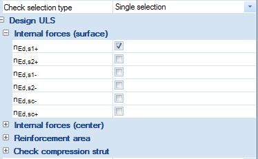
Single selection
only one item can be selected for displaying of results in numerical and graphical output. For instance on item (nEd1+) is selected and when another (As1+) is chosen the previous item is automatically deselected; all other groups on the same level are automatically collapsed.
Multi selection
two or more items can be selected for displaying of results. The new attribute Draw magnitude is visible for this option for selection, which type of value from the selected will be presented in graphical window, because only one value can be presented now in graphical output for 2D member:
| Single selection (nEd1+) |
Single selection (As1+) |
Multi selection (nEd1+) and (As1+) |
|---|---|---|
|
|
|
|
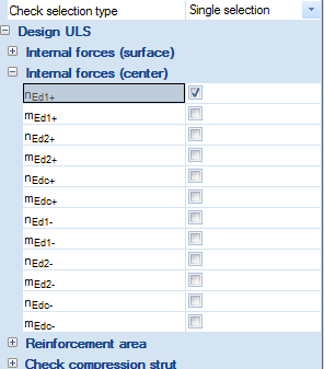
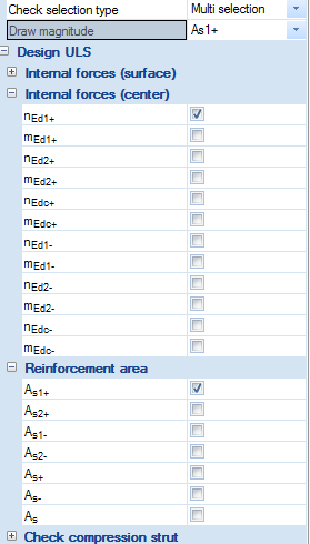
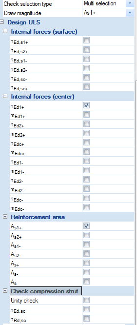
Default setting is Single selection, the group Internal force(surface) is expanded and first value from this group is on, see picture below
Navigator
Additionally, standard combobox Values are substituted by navigator (subgroups) where it is possible to select values for graphical presentation. The navigator has several levels (groups). In version 2013.1, there are the following levels
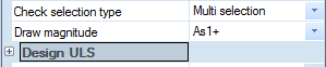
First level
there is only one item
Design ULS
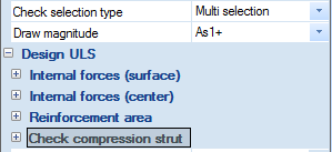
Second level
there are 4 subgroups. There is one table for each subgroup in standard numerical output
Internal forces(surface) – forces at surfaces of 2D element
Internal forces(center) – forces recalculated to centre of gravity of the cross-section of 2D members
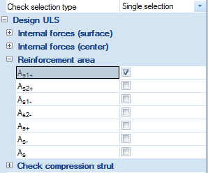
Reinforcement area – designed (required) area of the reinforcement
Check compression strut – check concrete compression strut
Third level
there are the following values, which can be presented too in graphical output
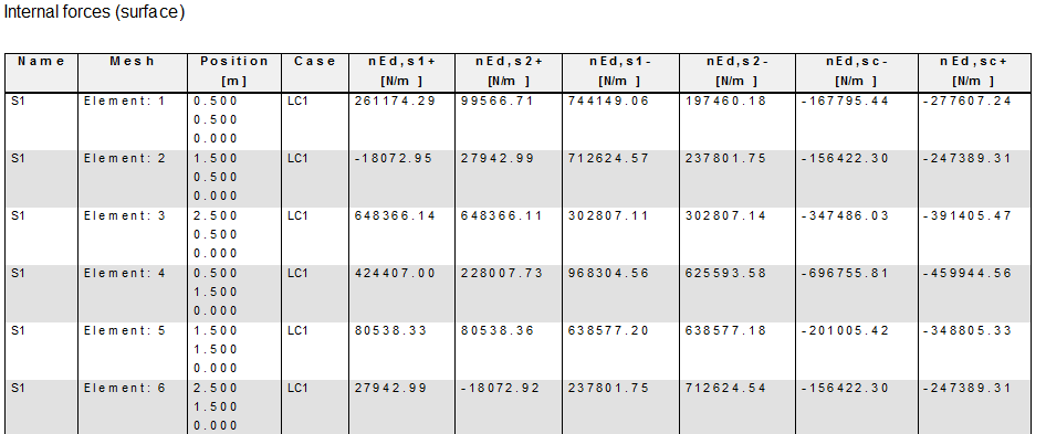
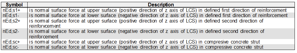
Internal forces(surface)
|
nEd,s1+ |
is normal surface force at upper surface (positive direction of z axis of LCS) in defined first direction of reinforcement |
|
nEd,s2+ |
is normal surface force at upper surface (positive direction of z axis of LCS) in defined second direction of reinforcement |
|
nEd,s1- |
is normal surface force at lower surface (negative direction of z axis of LCS) in defined first direction of reinforcement |
|
nEd,s2- |
is normal surface force at lower surface (negative direction of z axis of LCS) in defined second direction of reinforcement |
|
nEd,sc- |
is normal surface force at lower surface (negative direction of z axis of LCS) in compressive concrete strut |
|
nEd,sc+ |
is normal surface force at upper surface (positive direction of z axis of LCS) in compressive concrete strut |
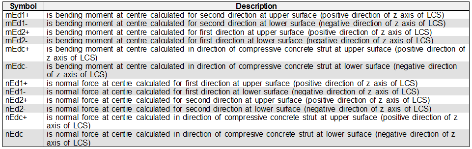
Check ULS Internal forces(centre)
|
nEd1+ |
is normal force at centre calculated for first direction at upper surface (positive direction of z axis of LCS) |
|
mEd1+ |
is bending moment at centre calculated for second direction at upper surface (positive direction of z axis of LCS) |
|
nEd2+ |
is normal force at centre calculated for second direction at upper surface (positive direction of z axis of LCS) |
|
mEd2+ |
is bending moment at centre calculated for first direction at upper surface (positive direction of z axis of LCS) |
|
nEdc+ |
is normal force at centre calculated for in direction of compressive concrete strut at upper surface (positive direction of z axis of LCS) |
|
mEdc+ |
is bending moment at centre calculated for in direction of compressive concrete strut at upper surface (positive direction of z axis of LCS) |
|
nEd1- |
is normal force at centre calculated for first direction at lower surface (negative direction of z axis of LCS) |
|
mEd1- |
is bending moment at centre calculated for second direction at lower surface (negative direction of z axis of LCS) |
|
nEd2- |
is normal force at centre calculated for second direction at lower surface (negative direction of z axis of LCS) |
|
mEd2- |
is bending moment at centre calculated for first direction at lower surface (negative direction of z axis of LCS) |
|
nEdc- |
is normal force at centre calculated for in direction of compressive concrete strut at lower surface (negative direction of z axis of LCS) |
|
mEdc- |
is bending moment at centre calculated for in direction of compressive concrete strut at lower surface (negative direction of z axis of LCS) |
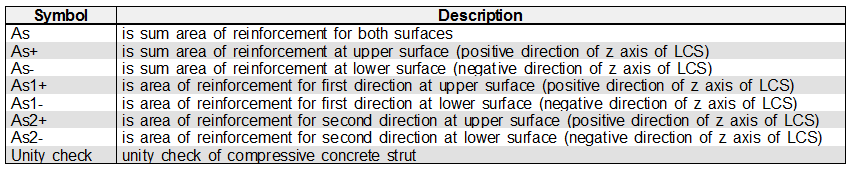
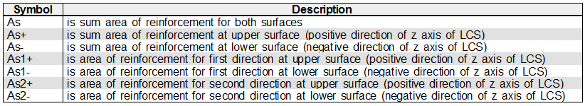
Reinforcement area
|
As1+ |
is area of reinforcement for first direction at upper surface (positive direction of z axis of LCS) |
|
As2+ |
is area of reinforcement for second direction at upper surface (positive direction of z axis of LCS) |
|
As1- |
is area of reinforcement for first direction at lower surface (negative direction of z axis of LCS) |
|
As2- |
is area of reinforcement for second direction at lower surface (negative direction of z axis of LCS) |
|
As+ |
is sum area of reinforcement at upper surface (positive direction of z axis of LCS) |
|
As- |
is sum area of reinforcement at lower surface (positive direction of z axis of LCS) |
|
As |
is sum area of reinforcement for both surfaces |
Check compression strut
|
Unity check |
is maximum unity check of compressive concrete strut from both surfaces |
|
nEd,sc |
is normal surface force in compressive concrete strut from the surface with greater value of unity check |
|
nRd,sc |
is design value of resistance of concrete compressive strut from the surface with greater value of unity check |
Graphically, three levels of navigator can be seen from the following figures
|
First level |
Second level |
Third level |
|---|---|---|
|
|
|
|
Drawing setup 2D
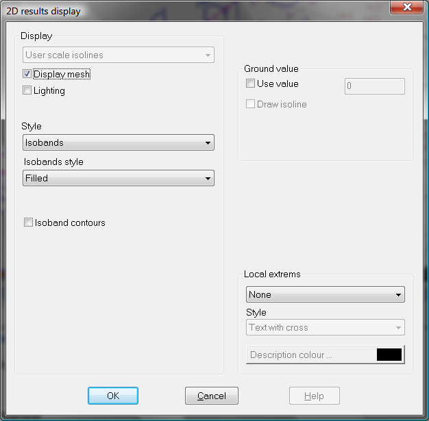
By selecting edit button for this parameter, a 2D results display dialog will be open. Here user may specify the representation of design results on 2D member. We can split this dialog into a four zones.
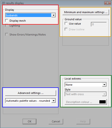
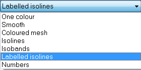
- Display = red (here user may define the main type of 2D design representation, he may choose to select one possibility from the list below)
- blue (where user may adjust type of representation selected in Display zone, the view of this zone may differ consequently to each type)
- green (here user may define to show or not to show local extremes and their appearance)
- yellow (it is possible to adjust the range of the scale and user defined isolines)
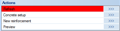
Action buttons
In the lower part of the Properties dialog are a few action buttons placed. User may find these buttons very useful.
Numerical output
Generally, there are available two levels of numerical output, which can be set via parameters Output (see chapter "Output"). These outputs are the following ones
Brief
one short table from all selected items (subgroups)
Standard
one table for each subgroup (4 tables are available)
Internal forces(surface) – the table is visible, if some values from this group is switched ON in the navigator
Internal forces (center) - the table is visible, if some values from this group is switched ON in the navigator
Reinforcement area - the table is visible, if some values from this group is switched ON in the navigator
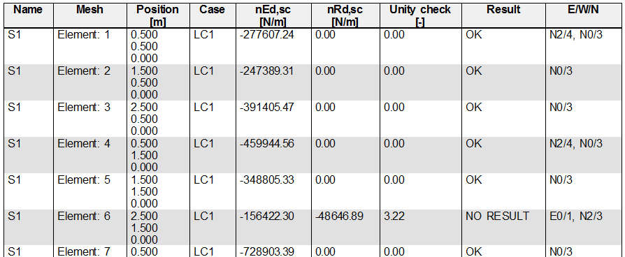
Check compression strut - the table is visible, if some values from this group is switched ON in the navigator
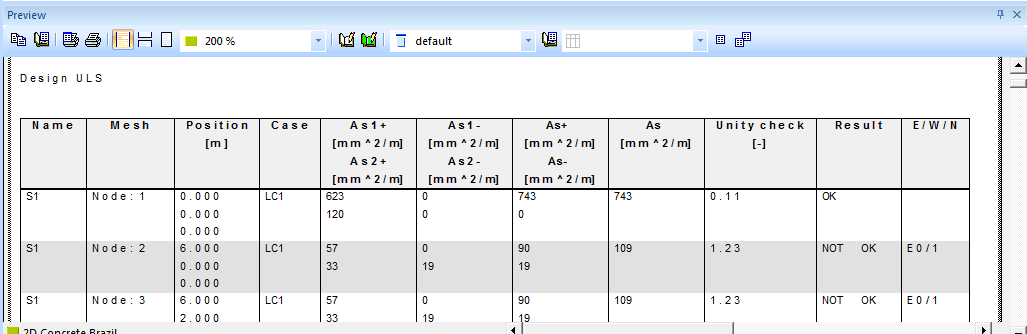
Example of Brief output
Example of Standard output for subgroup Internal force (surface)
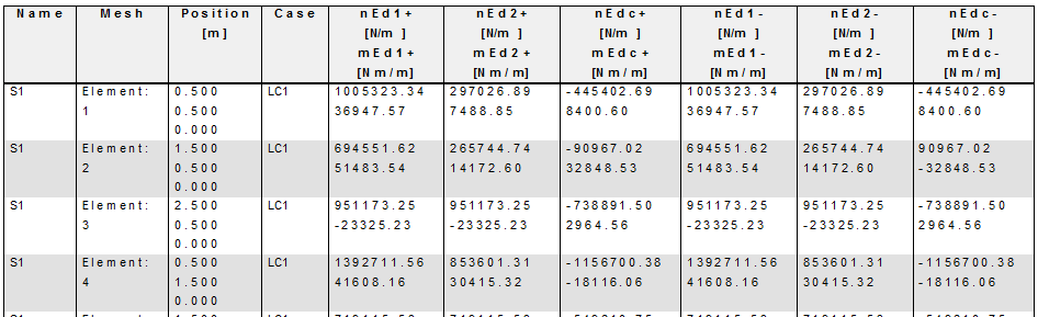
Example of Standard output for subgroup Internal force (centre)
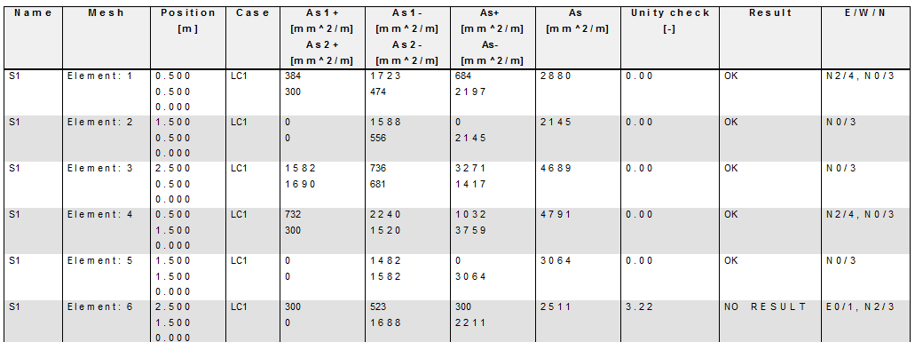
Example of Standard output for subgroup Reinforcement area
Example of Standard output for subgroup Check compression strut