|
N0/1
|
Note
|
The forces are zero
|
|
|
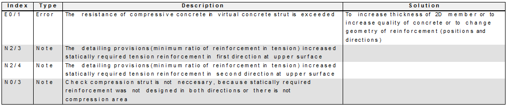
E0/1
|
Error
|
The resistance of the compressive concrete in the virtual concrete strut is exceeded
|
To increase the thickness of 2D member or to increase the quality of concrete or to change the geometry of reinforcement (position and directions)
|
|
E0/2
|
Error
|
The angle between directions of reinforcement at upper surface is lesser than minimum angle (15 deg)
|
To change direction of reinforcement at upper surface
|
|
E0/3
|
Warning
|
The position of lower reinforcement is above centre of 2D element
|
To increase thickness of the 2D member or to decrease concrete cover of reinforcement
|
|
E0/4
|
Warning
|
The position of upper reinforcement is under centre of 2D element
|
To increase thickness of the 2D member or to decrease concrete cover of reinforcement
|
|
E0/5
|
Error
|
The angle between directions of reinforcement at lower surface is lesser than minimum angle (15 deg)
|
To change direction of reinforcement at lower surface
|
|
N0/2
|
Note
|
The inner lever arm for recalculation of internal forces of was calculated according to formula z =0.9*d, because inner lever arm is not possible to calculate from plane of equilibrium in direction of principal moment (tensile reinforcement , compressive concrete fibre of plane of equilibrium was not found)
|
|
|
N0/3
|
Note
|
Check compression strut is not necessary, because statically required reinforcement was not designed in both directions or there is not compression area
|
|
|
N2/1
|
Note
|
The statically required tensile reinforcement in the first direction at lower surface was increased due to detailing provisions (minimum ratio of reinforcement)
|
|
|
N2/2
|
Note
|
The statically required tensile reinforcement in the second direction at lower surface was increased due to detailing provisions (minimum ratio of tensile reinforcement)
|
|
|
N2/3
|
Note
|
The statically required tensile reinforcement in the first direction at upper surface was increased due to detailing provisions (minimum ratio of tensile reinforcement)
|
|
|
N2/4
|
Note
|
The statically required tensile reinforcement in the second direction at upper surface was increased due to detailing provisions (minimum ratio of tensile reinforcement)
|
|
|
N2/5
|
Note
|
The statically required compressive reinforcement in the first direction at lower surface was increased due to detailing provisions (minimum ratio of compressive reinforcement)
|
|
|
N2/6
|
Note
|
The statically required compressive reinforcement in the second direction at lower surface was increased due to detailing provisions (minimum ratio of compressive reinforcement)
|
|
|
N2/7
|
Note
|
The statically required compressive reinforcement in the first direction at upper surface was increased due to detailing provisions (minimum ratio of compressive reinforcement)
|
|
|
N2/8
|
Note
|
The statically required compressive reinforcement in the second direction at upper surface was increased due to detailing provisions (minimum ratio of compressive reinforcement)
|
|
|
N2/9
|
Note
|
The statically required reinforcement in the first direction at lower surface was increased due to detailing provisions (minimum transverse reinforcement)
|
|
|
N2/10
|
Note
|
The statically required reinforcement in the second direction at lower surface was increased due to detailing provisions (minimum transverse reinforcement)
|
|
|
N2/11
|
Note
|
The statically required reinforcement in the first direction at upper surface was increased due to detailing provisions (minimum transverse reinforcement)
|
|
|
N2/12
|
Note
|
The statically required reinforcement in the second direction at upper surface was increased due to detailing provisions (minimum transverse reinforcement)
|
|
|
N2/13
|
Note
|
The statically required tensile reinforcement in the first direction at lower surface was increased due to detailing provisions (maximum spacing of main reinforcement)
|
|
|
N2/14
|
Note
|
The statically required tensile reinforcement in the second direction at lower surface was increased due to detailing provisions (maximum spacing of main reinforcement)
|
|
|
N2/15
|
Note
|
The statically required tensile reinforcement in the first direction at upper surface was increased due to detailing provisions (maximum spacing of main reinforcement)
|
|
|
N2/16
|
Note
|
The statically required tensile reinforcement in the second direction at upper surface was increased due to detailing provisions (maximum spacing of main reinforcement)
|
|
|
W2/1
|
Warning
|
The detailing provisions(maximum ratio of reinforcement) is exceeded in first direction at lower surface
|
To increase thickness of 2D member ,to increase quality of concrete or reinforcement or to change geometry of reinforcement (positions and directions)
|
|
W2/2
|
Warning
|
The detailing provisions(maximum ratio of reinforcement) is exceeded in second direction at lower surface
|
To increase thickness of 2D member ,to increase quality of concrete or reinforcement or to change geometry of reinforcement (positions and directions)
|
|
W2/3
|
Warning
|
The detailing provisions(maximum ratio of reinforcement) is exceeded in first direction at upper surface
|
To increase thickness of 2D member ,to increase quality of concrete or reinforcement or to change geometry of reinforcement (positions and directions)
|
|
W2/4
|
Warning
|
The detailing provisions(maximum ratio of reinforcement) is exceeded in second direction at upper surface
|
To increase thickness of 2D member ,to increase quality of concrete or reinforcement or to change geometry of reinforcement (positions and directions)
|