Design of longitudinal reinforcement
Procedure for design statically required reinforcement
The following preconditions are used for design statically required reinforcement
- The longitudinal area of reinforcement are designed only in two inputted direction. The different directions for lower and upper surface can be used
- The longitudinal reinforcement is designed without influence of shear effect
- The practical (user) reinforcement is not taken into account.
- Only two layers of reinforcement with different directions can be inputted
- The second layer of the reinforcement lies directly on the first layer
- The all layers of reinforcement is taken into account as main (major) reinforcement
- The direction angle of concrete strut will be optimalized to satisfy the condition of smallest value of force in such a direction.
The following procedure will be used for calculation:
- Definition of input value for calculation
- Calculate required area of reinforcement in all defined direction
- Check maximum force in concrete struts
Definition of input value for calculation
The following values has to be inputted for design of reinforcement:
|
nEdi± |
The dimensional normal force in i-th direction in centre of gravity |
|
mEdi± |
The dimensional bending moment force in i-th direction in centre of gravity |
|
nsurface,3+(-) |
The normal surface force in direction of compression concrete strut |
|
h |
thickness of 2D element |
|
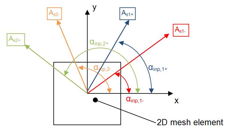
αinp,1(2)+ |
The first (second) inputted direction of calculation at upper surface defined from x axis of LCS of FEM element. The value is defined in Concrete setup. |
|
αinp,1(2)- |
The first (second) inputted direction of calculation at lower surface defined from x axis of LCS of FEM element. The value is defined in Concrete setup. |
|
d1(2)+(-) |
Diameter of longitudinal reinforcement in first(second) direction at upper(lower) surface. The value is defined in Concrete setup.
|
|
Cover+(-) |
Cover of longitudinal reinforcement at upper(lower) surface calculated to surface of the closer bar to the surface. The value is defined in Concrete setup. |
|
Redfcd |
Coefficient for reduction compressive concrete strength in concrete strut, see chapter "General". The value is defined in Concrete setup. |
Calculate required area of reinforcement in all defined direction
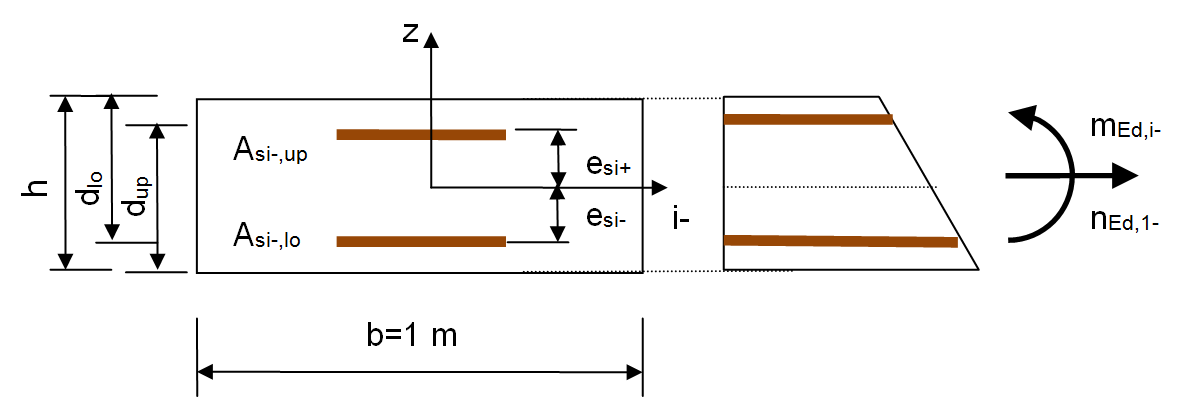
The required area is designed for both directions for lower and upper surface with following preconditions:
height of the cross-section equals to height of FEM element
width of the cross-section is 1m
- The distance of reinforcement in cross-section from centre of cross-section is the same for all direction of reinforcement
distance of first reinforcement: es1+(-) =0,5⋅h – [cover+(-) + 0,5⋅ds1+(-)]
distance of second reinforcement: es2+(-) =0,5⋅h – [cover+(-) + ds1+(-)+ 0,5⋅ds2+(-)]
- The reinforcement in each direction is designed for loading by normal force (nEdi±) and bending moment (mEdi±)
For each surface and each directions lower and upper reinforcement can be designed
|
Direction |
Direction at lower surface |
Direction at upper surface |
||
|
Reinforcement |
Direction 1 αinp,1- |
Direction 2 αinp,2- |
Direction 1 αinp,1+ |
Direction 2 αinp,2+ |
|
Lower |
As1-,lo |
As2-,lo |
As1+,lo |
As2+,lo |
|
Upper |
As1-,up |
As2-,up |
As1+,up |
As2+,up |
Note: If direction at upper and lower surface are the same the reinforcement will be designed only twice, else 4 times
The final area of reinforcement for the selected direction and selected surface is
|
First reinforcement at lower surface (As1-) |
As1-= max(As1-,lo, As1+,lo) |
|
Second reinforcement at lower surface (As2-) |
As2-= max(As2-,lo, As2+,lo) |
|
First reinforcement at upper surface (As1+) |
As1+= max(As1+,up, As1-,up) |
|
Second reinforcement at upper surface (As2+) |
As2+= max(As2+,up, As2-,up) |
Detailing provisions for design longitudinal reinforcement
After designed statically required longitudinal reinforcement, the detailing provisions for longitudinal reinforcement is checked. It follows, that
As1(2)+(-) ≥ Asmin,1(2)+(-)
As1(2)++ As1(2)- ≤ Asmax1
The following detailing provisions can be taken into account:
- minimum ratio of reinforcement in tension
- minimum ratio of reinforcement in compression
- maximum ratio of reinforcement
- minimum transverse reinforcement
- maximum spacing of main reinforcement
Check minimum ratio of reinforcement in tension
The minimum ratio of reinforcement in tension is taken into account in design of reinforcement if the check box Check minimum ratio of reinforcement in tension in Concrete setup is switched ON (see chapter "Detailing provisions") . The minimum area of reinforcement is taken into account, if statically required tensile reinforcement is nonzero. Minimum area of reinforcement in tension is calculated according to formula:
Asmin1t,1(2)+(-) = ρs,min,t⋅bw⋅h ( if As1(2)+(-) > 0 )
Asmin1t,1(2)+(-) = 0 ( if As1(2)+(-) = 0 )
where
|
ρs,min,t |
minimum ratio of reinforcement in tension from Concrete setup (see chapter "Detailing provisions")
|
|
bw |
the with of cross-section, bw = 1m |
|
h |
thickness of 2D FEM element in centre |
Note: If area of statically required reinforcement is lesser than minimum area of reinforcement in tension, program gives some Notes about it, see chapter "New system of warnings and errors"
Check minimum ratio of reinforcement in compression
The minimum ratio of reinforcement in compression is taken into account in design of reinforcement if the check box Check minimum ratio of reinforcement in compression in Concrete setup is switched ON (see chapter "Detailing provisions"). The minimum area of reinforcement is taken into account, if statically required compressive reinforcement is nonzero. Minimum area of reinforcement in compression is calculated according to formula:
Asmin1c,1(2)+(-) = ρs,min,c⋅bw⋅h ( if As1(2)+(-) > 0 )
Asmin1c,1(2)+(-) = 0 ( if As1(2)+(-) = 0 )
where
|
ρs,min,c |
minimum ratio of reinforcement in tension from Concrete setup (see chapter "Detailing provisions") |
|
bw |
the with of cross-section, bw = 1m |
|
h |
thickness of 2D FEM element in centre |
Note: If area of statically required reinforcement is lesser than minimum area of reinforcement in compression, program gives some Notes about it, see chapter "New system of warnings and errors"
Check maximum ratio of reinforcement
The maximum ratio of reinforcement is checked in design of reinforcement if the check box Check maximum ratio of reinforcement in Concrete setup is switched ON (see chapter "Detailing provisions"). The following condition has to be fulfilled.
- If directions of reinforcement of upper and lower surface are the same
As1(2)++ As1(2)- ≤ Asmax1 = ρs,max⋅bw⋅h
- If directions of reinforcement of upper and lower surface are different
- check for direction at upper surface
As 1(2)++ Σ As i-⋅cos2(αinp1(2)+ - αinp,i-)≤ As,max1 = ρs,max⋅bw⋅h (i =1,2)
- check for direction at lower surface
As 1(2)-+ Σ As i,+⋅cos2(αinp1(2)- - αinp,i+)≤ As,max1 = ρs,max⋅bw⋅h (i =1,2)
where
|
ρs,max |
maximum ratio of reinforcement from Concrete setup (see chapter "Detailing provisions")
|
|
bw |
the with of cross-section, bw = 1m |
|
h |
thickness of 2D FEM element in centre |
|
As 1(2)-(+) |
statically equired designed area of reinforcement in first(second) direction for lower(upper) surface |
|
αinp1(2)-(+) |
first(second) direction of reinforcement lower(upper) surface |
Note: If area of statically required reinforcement is bigger than maximum area of reinforcement, program gives some Warning about it, see chapter "New system of warnings and errors"
Check minimum transverse reinforcement
The minimum transverse reinforcement will be taken into account in design of reinforcement if the check box Check minimum transverse reinforcement in Concrete setup is switched ON (see chapter "Detailing provisions"). The minimum area of transverse reinforcement is taken into account if area of statically required reinforcement in one direction at one surface is nonzero . The minimum area of reinforcement in this case is calculated according to formula
- for upper surface
Asmin2,1(2)+= ρs,min2⋅max(As1+, As2+) ( if As1+ > 0 or As2+ > 0)
Asmin2,1(2)+= 0 ( if As1+ = 0 and As2+ = 0)
- for lower surface
Asmin2,1(2)-= ρs,min2⋅max(As1-, As2-) ( if As1- > 0 or As2- > 0)
Asmin2,1(2)-= 0 ( if As1- = 0 and As2- = 0)
where
|
ρs,min2 |
minimum transverse reinforcement from Concrete setup (see chapter "Detailing provisions")
|
|
bw |
the with of cross-section, bw = 1m |
|
h |
thickness of 2D FEM element in centre |
|
As 1(2)-(+) |
statically required designed area of reinforcement in first(second) direction for lower(upper) surface |
Note: If area of statically required reinforcement is lesser than minimum area of transverse reinforcement, program gives some Notes about it, see chapter "New system of warnings and errors"
Check maximum spacing of main reinforcement
The maximum spacing of main reinforcement will be taken into account in design of reinforcement if the check box Check maximum spacing of main reinforcement in Concrete setup is switched ON (see chapter "Detailing provisions"). The minimum area of reinforcement calculated from maximum spacing of main reinforcement is taken into account in case that area of reinforcement in checked direction and surface is nonzero. The minimum are of reinforcement is calculated according to formula
Asmin3,1(2)+(-) = 0,25⋅π⋅ds2⋅1m/smax ( if As1(2)+(-) > 0 )
Asmin3,1(2)+(-)= 0 ( if As1(2)+(-) = 0 )
where
|
smax |
maximum spacing of main reinforcement in [m] smax = max(xA,xB*h)
|
|
xA,xB |
coefficient for calculation maximum spacing of main reinforcement loaded from Concrete setup, see chapter "Detailing provisions" |
|
ds |
diameter of main reinforcement in checked direction and surface loaded from concrete setup |
Note: The all directions for both surfaces will be taken into account as main reinforcement
Note: If area of statically required reinforcement is lesser than minimum area of reinforcement calculated from maximum spacing of reinforcement reinforcement, program gives some Notes about it, see chapter "New system of warnings and errors"
Final value of minimum area of reinforcement from detailing provisions
The final value of minimum area of reinforcement from detailing provisions is calculated according to formulas:
- for tensile reinforcement:
Asmin,1(2)+(-) = max[Asmin1t,1(2)+(-); Asmin2,1(2)+(-); Asmin3,1(2)+(-)]
- for compressive reinforcement:
Asmin,1(2)+(-) = max[Asmin1c,1(2)+(-); Asmin2,1(2)+(-); Asmin3,1(2)+(-)]