5.3 Member data 2D (walls, plates)
By creating member data user will over change default global settings with local settings defined for selected members. Simply said, where user doesn’t want use global concrete settings, user creates local concrete settings by defining member data.
This member data may be created by selecting item in Concrete tree and choosing the proper 2D member, where this data want to be defined. These newly created settings will be loaded from default global settings It is possible to change them to fit user needs.
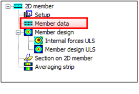
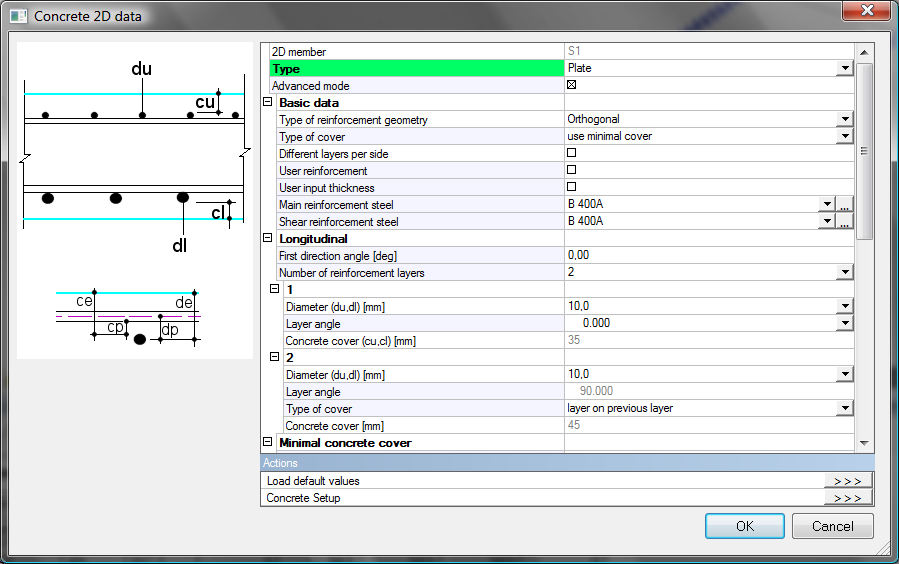
After selection of a 2D member or 2D sub region, is Concrete 2D data dialog displayed and local settings may be defined and confirmed.
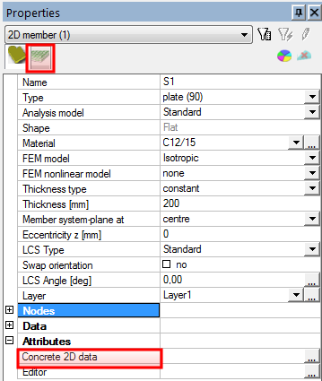
When member data are created, a new folder will appear in member properties and will be shown in Attributes of the member too.
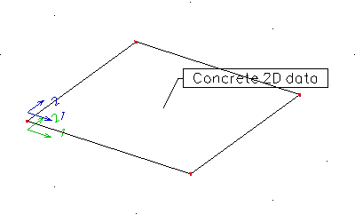
After definition of Member data is graphical mark (label) displayed together with the arrows describing reinforcement directions on the member as well. Notice, that arrows will be visible only when mesh is created. After clicking on these marks is user allowed editing the appropriate attributes in member properties window. Content of the label is also possible to edit through Concrete folder in View parameters setting dialog.
|
Orthogonal.,2 directions, same layers |
User .,3 directions, different layers |
|---|---|
|
|
|
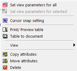
Local settings were changed since SCIA Engineer version 2010 to attributes. This change enables editing of these settings directly through the properties of selected member. It is possible to manipulate with these settings as with all others attributes by functions Copy attributes and Move attributes in:

- member menu after choosing attribute and right clicking
It is possible to edit these parameters in Member data.
5.3.1 Type
This represents the 2D member type. Default value depends on type defined in member’s properties.
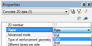
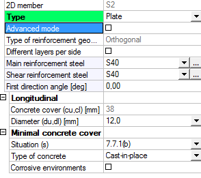
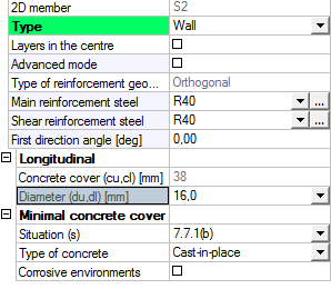
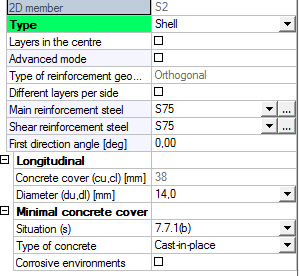
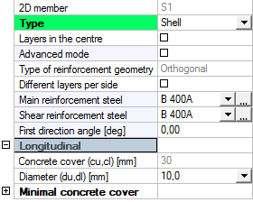
There are three types supported for this attribute (plate, wall, shell). The change of type attribute does not influence the analysis model, but influences only presentation and definition of the parameters in the member data properties. In table below are displayed Member data properties for each type selected, without advance mode activated.
|
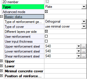
Plate |
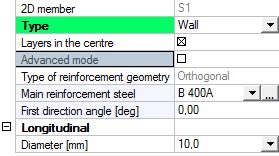
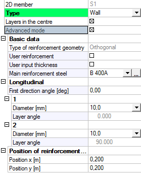
Wall |
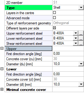
Shell |
|---|---|---|
|
|
|
|
From the table above it is obvious that type:
- Plate enables to define different parameters for each member surface (upper, lower) by check box Different layers per side, but it is not possible to define only one layer of the reinforcement in the centre by check box Layers in the centre.
- Wall does not enable to define different parameters for each member surface (upper, lower) by check box Different layers per side, but it is not possible to define only one layer of the reinforcement in the centre by check box Layers in the centre.
- Shell enables to define different parameters for each member surface (upper, lower) by check box Different layers per side and it is also possible to define only one layer of the reinforcement in the centre by check box Layers in the centre.
5.3.2 Different layers per side
This attribute enables to define different parameters for upper and lower surfaces and its reinforcement layers. By activating this attribute user will be able to define different reinforcement material, different directions and different diameters for each surface. This attribute is available only when Type is set to Plate or Shell.
|
Different layers per side off |
Different layers per side on |
|
|
|
As you can see original tree item Longitudinal is divided into item Upper and Lower. If an advanced mode will be activated too, then another items Number of reinforcement layers and its directions will be added.
5.3.3 Layers in the centre
In the real life project we come across with 2D members which have very small thickness, which does not allow defining reinforcement layers for both surfaces. It is necessary to design only one layer of reinforcement which lies in the centre of gravity of the member. It is possible to design only one layer of reinforcement by activating attribute Layers in the centre. This attribute is available only when Type is set to Wall or Shell and when it is checked, many parameters in member data are deactivated.
It is not possible to change attribute type of reinforcement geometry attribute. Only orthogonal direction of reinforcement layers is supported.
Only two reinforcement layers are allowed. One lies just above the centre of gravity location and the other one lies just bellow it.
|
Layers in the centre with Advanced mode off |
Layers in the centre with Advance mode on |
|---|---|
|
|
|
5.3.4 Advanced mode
This attribute is a filter for displaying the parameters in member data properties. If it is switched off, then only basic parameters from global settings (Design defaults) are displayed together with reinforcement material parameters, which might be edited. Groups Longitudinal and Minimal concrete cover with the very basic parameters are displayed.
When it is activated then user may edit all available parameters. Those parameters are sorted to a few groups:
5.3.4.1 Group Basic data
In this group are basic attributes and parameters for reinforcement design. As you can see from the picture user can edit reinforcement geometry, type of concrete cover and reinforcement materials here. Also Different layers per side, User reinforcement and User input thickness attributes are here.
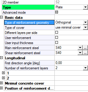
5.3.4.1.1 Type of reinforcement geometry
There are two types of reinforcement geometry in SCIA Engineer:
- Orthogonal (default) where user can define only one direction angle for first reinforcement layer. The second reinforcement layer direction will always be perpendicular to the first one. Default value for first direction angle is loaded from global settings.
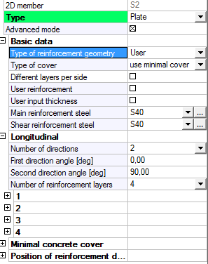
- User where it is allowed to define two or three direction angles for each reinforcement layer separately. Number of directions may be edited by same parameter in Longitudinal folder.
|
Orthogonal |
User 2 directions |
User 3 directions |
|---|---|---|
|
|
|
|
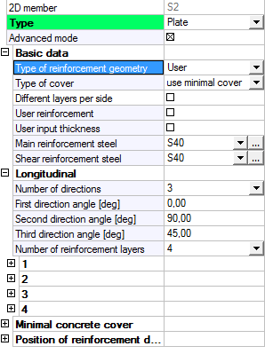
Minimal difference between two reinforcement directions defined directly by user, must be 30 degrees at minimum. If the difference is smaller, then the reinforcement design will end up with Error 61 (General error in input data).
5.3.4.1.2 Type of cover
It is possible to change the way, concrete cover is calculated. Two basic types of cover are supported (see chapter "4.2 Concrete setup for 2D members" and "5.2 Member data 1D (beams, beams as slab, columns)"):
- Use minimal cover enables SCIA Engineer software evaluates all appropriate parameters and calculates minimal possible cover according to the selected Code. This will be the minimal value possible.
- User, where Concrete cover parameters in Longitudinal folder will be activated and user is allowed to use his own values
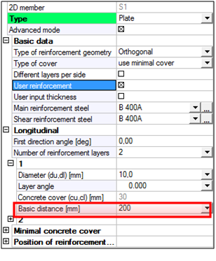
5.3.4.1.3 User reinforcement
User reinforcement is defined by new parameter Basic distance in Longitudinal folder, where user defines axial distance of reinforcement bars. It is possible to define different value for each reinforcement direction.
It is possible to set this attribute on only in case that there is no user reinforcement defined by 2D region or Free bars on selected 2D member or its sub region.
User reinforcement defined by Member data is same for whole 2D member surface. If user wants to change Basic distance value only on a part of the 2D member, then he needs to create sub region, where this parameter may be defined separately.
If user reinforcement is already active on a certain member and then user defines user reinforcement by 2D region or by free bars, then the user reinforcement defined in Member data will be deleted.
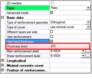
5.3.4.1.4 User input thickness
SCIA Engineer software enables to set different thickness for 2D member or its sub region, than in model is defined. The big advantage of this feature is that it is possible to run reinforcement design for different thickness, without the need of deleting calculation results together with inner forces. The importance of this function is directly proportional to the size of the structure in the project, where calculation of inner forces may take very long time. What is important is, that user must remember the fact, that self weight of the changed member is not adjusted by changed thickness by this function and remains the same as originally defined.
User defined thickness of 2D member or its sub region is possible to edit by new parameter Thickness. This parameter will be displayed after switching on attribute User input thickness.
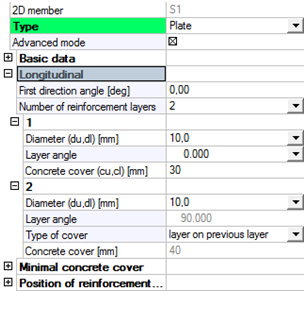
5.3.4.2 Group Longitudinal
In this group are parameters for each reinforcement direction such as number of layers in each direction, their angles, bar diameters and eventually distances between them. Also very important parameter which influences concrete cover for each layer is here. Longitudinal group, which defines parameters for both surfaces may be split into Upper and Lower group, when attribute Different layers per side is switched on. The appearance of this folder may differ quite a lot depending on activated attributes and defined parameters
|
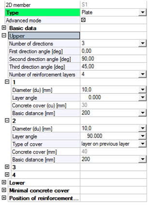
Longitudinal 2 directions, 2 layers, user cover |
Upper 3 directions, 4 layers, minimal cover |
|---|---|
|
|
|
5.3.4.2.1 Number of directions
By setting attribute Type of geometry to User, a new parameter Number of directions will be displayed in Longitudinal group. User is able to choose from two or three directions, where reinforcement will be created. According to the choice, user is able to define appropriate number of direction angles
5.3.4.2.2 Direction angles
As it was mentioned before, these are the values with direction angles. It may be one up to three. Default value for first direction angle is loaded from global settings. These direction angles are used only for reinforcement layers angles definition. It does not mean that this is angle of first, second or third reinforcement layer. User selects direction for each layer afterwards.
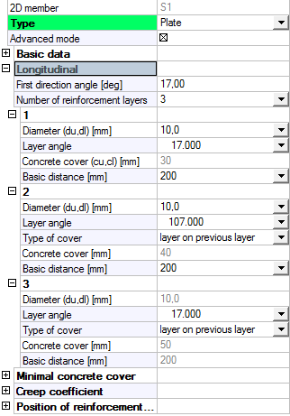
5.3.4.2.3 Number of reinforcement layers
User is allowed through member data to define more reinforcement layers for each member or sub region surface. Minimal amount of reinforcement layers is set by number of defined directions (see above). Maximal number of reinforcement layers for one surface is 10.
For each reinforcement layer is necessary to define its bar diameter, direction angle, type of cover, eventually Basic distance parameter.
5.3.4.2.4 Diameter
Reinforcement bar diameter is defined only for every first reinforcement layer in each direction. Default value is loaded again from global settings. The other layers in same direction has this parameter disabled (not possible to edit)
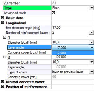
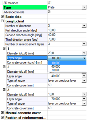
5.3.4.2.5 Layer angle
It is possible to choose from defined direction angles in this combo box. These angles were defined in root of Longitudinal group, eventually in root of Upper or Lower groups.
|
Orthogonal geometry 2 directions |
User geometry 3 directions |
|
|
|
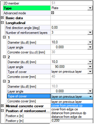
5.3.4.2.6 Type of cover
Concrete cover, which is a distance from outer reinforcement surface to closer surface of the member, is determined by this parameter. This value can be automatically calculated by the software for the first reinforcement layer. This calculation will respect values from group Minimal concrete cover (see chapter "4.2 Concrete setup for 2D members" and "5.2 Member data 1D (beams, beams as slab, columns)"). User may also define his own value for concrete cover. For this feature, attribute Type of cover in Basic data group must be switched on.
Location of other reinforcement layers depends on Type of cover for each of them. It is possible to define different Type of cover for each reinforcement layer. User can choose from these types:
- Layer on previous layer: One layer is laid on the other one.
- Cover from previous: The user defines the cover from the previous layer. The cover is measured from a surface of one reinforcement bar to the surface of the other bar.
- Cover from edge: The user defines the cover from the edge of the slab.
- Distance from previous: The user defines the distance from the previous layer. The distance is measured from the centre of one reinforcement bar to the centre of the other bar.
- Distance from edge: The user defines the distance from the edge of the slab.
Here is the description picture for all Types of cover. Turquoise line at the top represents 2D member surface.

5.3.4.2.7 Concrete cover (cu)
Shows or provides place for the input of cover value itself.
5.3.4.2.8 Basic distance
If the attribute User reinforcement from Basic data group is switched on, than Basic distance parameter is active and user may define and edit its value. As it was mentioned before, it represents axial distance between two reinforcement bars and it is defined only for every first reinforcement layer in each direction. For other reinforcement layers in already defined direction software sets the same value.
During reinforcement design only certain number of reinforcement layers is being input. This certain number equals to the number of defined directions. This means that if more reinforcement layers are defined in one defined direction, then for design is being input:
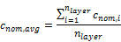
- Average concrete cover calculated from all reinforcement layers in that direction
- User reinforcement area calculated from the first reinforcement layer (after assigning reinforcement layer to direction which has already one layer defined, it is possible to edit only concrete cover of this new layer
The conclusion from this is that more layer reinforcement model may be substituted with only one layer with adjusted value of concrete cover.
If average concrete cover value for upper or lower surface is equal or even bigger than half of member thickness, design will not be possible and it will end up with Error 61 (General error in input data).
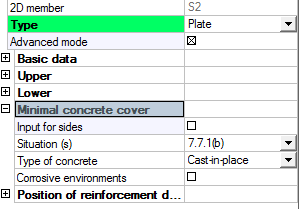
5.3.4.3 Group Minimal concrete cover
Here in this group are parameters which influence the value of minimal cover calculated by the software. It is also possible to define different parameters for upper and lower surface separately by switching on attribute Input for side. User can edit Situation, Type of concrete and Corrosive environments.
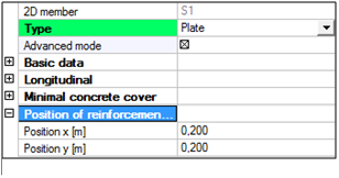
5.3.4.4 Group Position of reinforcement direction arrows
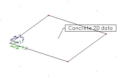
Only two parameters are in this group. By editing default values, user can move the location of the direction arrow marks, along the 2D member or its sub region. It is not possible to set coordinates out of the 2D member or sub region. Arrow directions are always related to coordinate system of appropriate mesh element, where arrows are located. From this reason, only when mesh is created, direction arrows are visible.
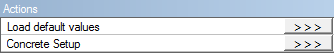
5.3.4.5 Action buttons
Just bellow all Member data attributes and parameters, there are two action buttons, which user might sometimes find useful:
- Load default values, which will restore default settings from global settings for appropriate parameters such as, diameter, angle, etc.
- Concrete Setup, which will open dialog with global settings, while items in this dialog are filtered according to the member type and member check.
Parameters in member data, with the grey background, are parameters visible only when Advanced mode is switched on.
5.3.5 Tips & tricks
5.3.5.1 Member data labels
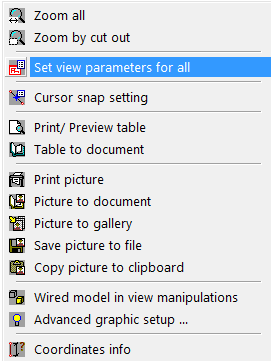
If a Member data are defined for certain 2D member or its sub region, then graphical mark (label) is displayed together with the arrows describing reinforcement directions and layers on the member. Only name of the attribute is displayed by default (Concrete 2D data), but this description is possible edit or modify in View parameters setting dialog. It might be accessed by:
- clicking by right mouse button on graphical window, and choosing item Set view parameters for all
- using an icon Fast adjustment of view parameters on whole model, which is above command prompt, and selecting Setup dialog possibility
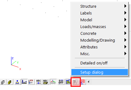
After that View parameters setting dialog, affecting whole model, is displayed and user can find parameters for concrete structure are in folder Concrete
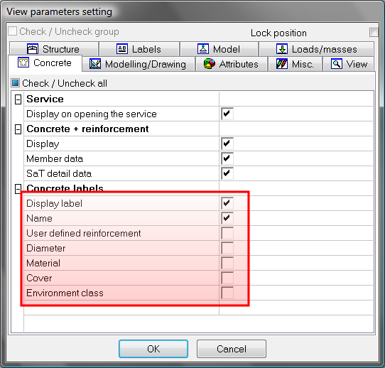
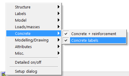
Member data can be switched on or switched off by two ways:
- by checking and unchecking check box Display label from dialog above
- by selecting Concrete label button in Fast adjustment of view parameters on whole model menu (see picture below)