Displaying the internal forces on slabs (PPEv17)
The procedure to display the internal forces
-
Open service Results.
-
Select function 2D members > 2D Internal forces.
- Refresh
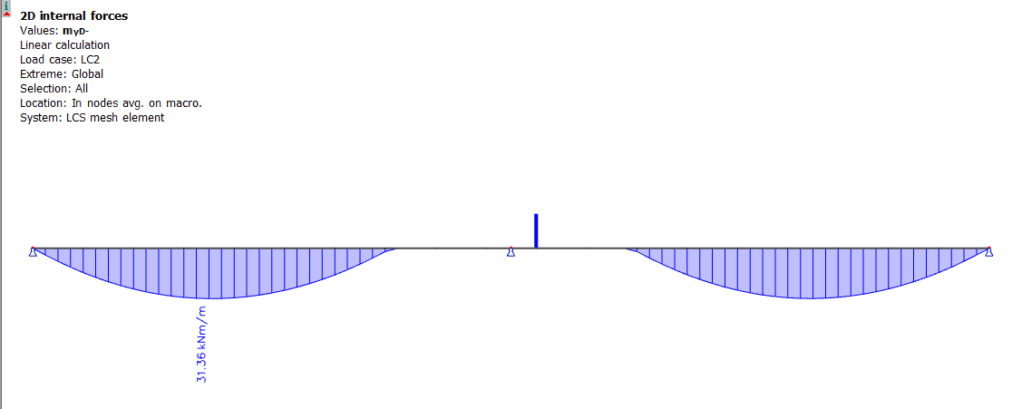
Parameters for 2D results
Description for basic settings of 2D results can be found here: Selection and filter ; Loading
Special settings for 2D results are:
|
Averaging of peak |
To activate the averaging algorithm |
Displaying the averaged results, Averaging strips |
| Rib | Turns ON/OFF rib effect on slab | Calculation of internal forces in ribs |
|
Location |
Sets how the results will be displayed related to mesh |
Averaging of results in FE nodes |
|
Type of values |
2D internal forces provides three types of values - basic, principal, elementary design |
Calculated results for 2D members |
|
Standard result |
Shows results on slab plane, drawing is handled by 2D drawing setup | 2D drawing setup |
| Result on section | Shows results on sections, drawing is handled by 1D drawing setup (same as for any other 1D member) | 1D drawing setup |
| Result on edges | Shows results on slab edges, drawing is handled by 1D drawing setup (same as for any other 1D member) | 1D drawing setup |
Type of forces
As mentioned above, there are three different types of force. The following tables summarise individual options.
Basic magnitude
Project: plate
mx
bending moment of 2D member in x direction
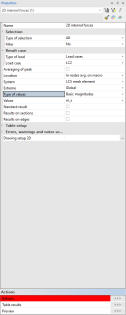
my
bending moment of 2D member in y direction
mxy
torsion moment of 2D member
vx
shear force perpendicular to plane of 2D member in x direction
vy
shear force perpendicular to plane of 2D member in y direction
Project: wall
nx
normal force of 2D member in x direction
ny
normal force of 2D member in y direction
nxy
membrane shear force of 2D member
Project: general (shell)
mx
bending moment of 2D member in x direction
my
bending moment of 2D member in y direction
mxy
torsion moment of 2D member
vx
shear force perpendicular to plane of 2D member in x direction
vy
shear force perpendicular to plane of 2D member in y direction
nx
normal force of 2D member in x direction
ny
normal force of 2D member in y direction
nxy
membrane shear force of 2D member
Principal magnitude
Note: Lower index "m" at the quantity name means the membrane component. Lower index "b" at the quantity name means the bending component.
Project: plate
|
m1, m2 |
principal moments |
|
alfa |
angle between the direction of m1 and planar axis xP |
|
mtmax |
maximal torque moment |
|
qmax |
maximal shear force |
Project: wall
|
n1, n2 |
principal axial forces |
|
alfa |
angle between the direction of n1 and planar axis xP |
Project: general (shell)
|
m1, m2 |
principal moment |
|
alfab |
angle between the direction of m1 and planar axis xP |
|
qmax-b |
maximal shear force from bending effects |
|
beta |
angle between the direction of qmxo and planar axis xP |
|
n1, n2 |
principal axial forces |
|
alfam |
angle between the direction of n1 and planar axis xP |
|
qmax-m |
maximal shear force from membrane effects |
Design magnitude
|
Project: plate |
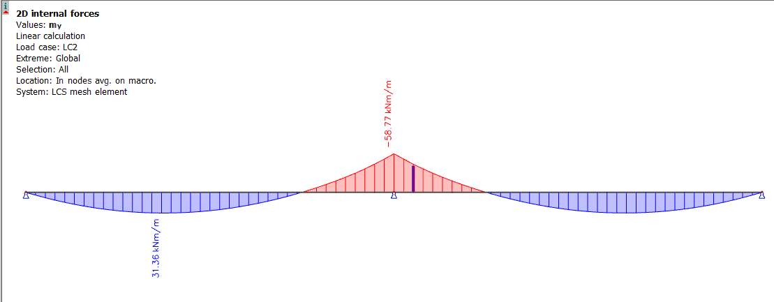
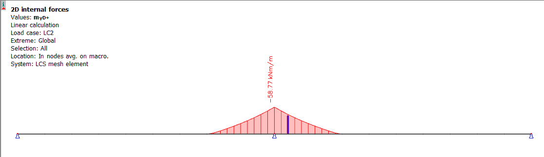
mxD+, myD+, mcD+, mxD–, myD–, mcD– |
|
Project: wall |
nxD, nyD, ncD |
|
Project: general (shell) |
mxD+, myD+, mcD+, mxD–, myD–, mcD–, nxD, nyD, ncD |
Only relevant design moments are drawn per surface. For upper top surface we show only negative values, and for bottom we show only positive values.
Note: Starting with version 18.0, when viewing design moments for the top surface, if the type of load is set to 'Class', setting the envelop to 'Minimum' will display the highest negative values resulting from the combinations in the class and setting the envelop to 'Maximum' will display the lowest negative values. This differs from the methodology in 17.9 and prior, where all values were shown as positive and setting the envelop to 'Maximum' displayed the highest values.
In case of result on section we also respecting general rule of drawing the negative bending moment up (as it is relevant for upper surface) and positive moment down (as it is relevant only for bottom surface)
Design forces in a wall are in the middle plane.
Corresponding surface of action of design moments in shells is given directly by the sigh of the moment.
See also chapters Principal internal forces and Design internal forces.
See also chapter Style of isolines.