Subsoil in the 3D model
The subsoil in the 3D window is defined as a soil surface and soil borehole. The geologic profile is defined for each soil borehole. The position and the composition of the geologic profiles provide information about subsoil.
Soil borehole
The borehole is available in the project only when the functionality Soil interaction is checked.
The special property in the inserting dialogue converts standard borehole to the Sand-gravel pile. See more in the separate chapter.
Soil types according to ČSN EN 73 1001
| Fine-grained soils | Sands | Gravel | |||
| F1(MG) | loam, fine-grained | S1(SW) | sand, well-grained | G1(GW) | gravel well-grained |
| F2 (CG) | clay, gravelly | S2(SP) | sand, poorly-grained | G2(GP) | gravel poorly-grained |
| F3 (MS) | loam, sandy | S3(S-F) | sand, with fine-grained soil | G3(G-F) | gravel with fine-grained soil |
| F4 (CS) | clay, sandy | S4(SM) | sand, with loam | G4(GM) | gravel, with loam |
| F5 (ML) | loam, small plasticity | S5(SC) | sand, with clay | G5(GS) | gravel, with clay |
| F5 (MI) | loam, middle plasticity | ||||
| F6 (CL) | clay, small plasticity | ||||
| F6 (CI) | clay, middle plasticity | ||||
| F7 (MH) | loam, high plasticity | ||||
| F7 (MV) | loam, very high plasticity | ||||
| F7 (CH) | loam, extremly high plasticity | ||||
| F8 (CV) | clay, very high plasticity | ||||
| F8 (CE) | clay, extremly high plasticity | ||||
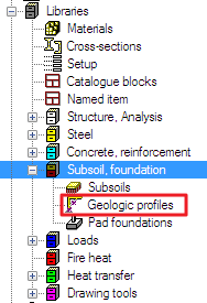
Geologic profile
All profiles are saved to the Geologic profiles library. The geologic profiles can be imported or exported by the DB4 format.
The borehole profile is defined as a simple grid with the preview. Each row represents one layer of soil with the same properties.
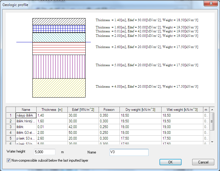
Each layer is defined by the soil parameters:
Name:
Specify the name of the layer
Thickness (m):
thickness of the layer
Edef:
The module of deformation Edef is defined as deformation characteristic of the soil. It is a ratio of the normal stress increment to the increment a linear transformation. For geotechnical categories 1 and 2 the indicative value from e.g. ČSN 73 1001 can be used, for category 3 a survey should be carried out to provide for the value. The value Em from Eurocode 7 can be used instead of Edef.
Edef according to ČSN 73 1001:
| Class of the subsoil | Edef (MPa) |
|---|---|
| F6-F8 (soft, medium consistency) | 1,5-4 |
| F6-F8 (stiff consistency) | 6-8 |
| F6-F8 (hard consistency) | 10-15 |
| F3-F5 (soft, medium consistency) | 3-5 |
| F3-F5 (stiff consistency) | 8-10 |
| F3-F4 (hard consistency) | based on survey |
| F5 (hard consistency) | 10-20 |
| F1, F2 (soft, medium consistency) | 5-15 |
| F1, F2 (stiff consistency) | 12-25 |
| F1, F2 (hard consistency) | based on survey |
| S4, S5 |
5-12 |
| S3 | 12-19 |
| S2 | 15-35 |
| S1 | 30-60 |
| G5 | 40-60 |
| G4 | 60-80 |
| G3 | 80-90 |
| G2 | 100-190 |
| G1 | 250-390 |
| R6 | 10-75 |
| R5 | 20-250 |
| R4 | 40-750 |
| R3 | 70-2500 |
| R2 | 130-7500 |
| R1 | 250-25000 |
The Edef for R is derived from the number of discontinuous parts in the soil.
Poisson:
Poisson’s ratio, coefficient of transverse deformation, an indicative value or experimentally found value can be used, predefined range is 0 – 0.5
Poisson according to ČSN 73 1001:
| Class of the subsoil | Poisson ν |
|---|---|
| F8 (soft, medium, stiff consistency) | 0,42 |
| F8 (hard consistency) | based on survey |
| F5-F7 (soft, medium, stiff consistency) | 0,40 |
| F5-F7 (hard consistency) | based on survey |
| F1-F4 (soft, medium, stiff consistency) | 0,35 |
| F1-F4 (hard consistency) | based on survey |
| S5 | 0,35 |
| S4, S3 | 0,30 |
| S1, S2 | 0,28 |
| G4, G5 | 0,30 |
| G3 | 0,25 |
| G1, G2 | 0,20 |
| R6 | 0,40-0,25 |
| R4, R5 | 0,30-0,20 |
| R3 | 0,25-0,15 |
| R1, R2 | 0,20-0,10 |
Dry weight:
weight for the dry soil, normally within the range from 18 to 23 kN/m3, range is 0 – 10000000000 kN/m3
Wet weight:
weight for the wet (saturated) soil, this value is mostly about 2-3 kN/m3 higher than the dry weight, range of the values is 10 – 10000000 kN/m3
m coefficient:
structural strength coefficient, according to the Eurocode7 is 0,2 (ČSN 73 1001 defines a table). The m coefficient may be modified for the whole Eurocode.
Coefficient m according to ČSN 73 1001:
| Class of the subsoil | m |
|---|---|
| F1-F8 with Edef<4MPa, not over consolidated and soft or solid consistency R1, R2 and R4, R5 not affected by erosion |
0,1 |
| F1-F8 which don’t belong to the first group S1, S2, G1, G2 under the water level R3 |
0,2 |
| S1, S2, G1, G2 above the water level S3-S5 G3-G5 R4, R5 which don’t belong to the first group |
0,3 |
| R6 | 0,4 |
| Loess, loess loam | 0,5 |
Geologic profile must be defined up to such a depth where the bearing pressure is still active, otherwise the program does not have sufficient information.
The defined parameters are displayed in the library as properties.
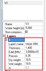
The height of the underground water is defined by the value in the properties. It is a positive value but it represents the depth.
Non-compressible subsoil below the last inputted layer

The checkbox “Non-compressible …” can be used if the soil below the last layer is non-compressible. The system applies coefficient of depth reduction ϰ2 in this case (calculation of ϰ 2 can be found in ČSN 73 1001, art. 80). This option is recommended when the non-compressible layer is placed in a small depth under the borehole.
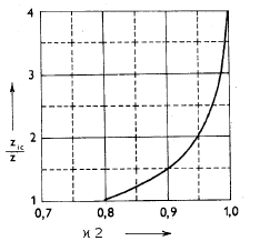
Calculation of ϰ 2 according to ČSN 73 1001:
ϰ 2=1-exp((zic/z) ln0,25 + ln0,8)
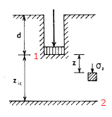
2 – non-compressible layer
zic – is the depth under the foundation base to the non-compressible layer
z – is the depth from the foundation base to the level where the contact stress σz should be calculated
The contact stress σz will be calculated by the reduced depth zr2= ϰ 2*z where z is the depth under the foundation base.
Properties of the borehole profile
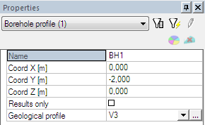
The borehole is defined by the geologic profile and the inserting point in the 3D window. The properties contain only name, its coordinates, the borehole profile and the checkbox Results only.
Settlement input data
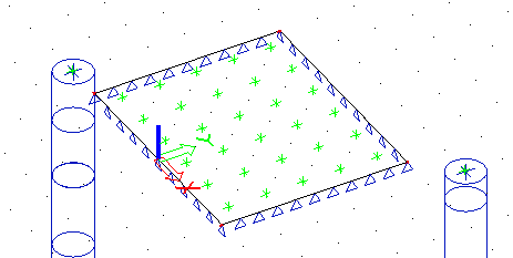
Settlement is calculated for each mesh element (in its center of gravity) and for each borehole inserting point. The checkbox Results only exclude a borehole inserting point from the input data. It means that the point is used for the calculation of settlement but the geologic profile is not taken into account for the layers approximation.
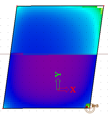
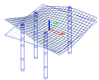
The nodes for the settlement calculation (green vertexes):
Geological areas
The main geological surface = area is calculated and displayed automatically. It is possible to create more areas in the main one.
Layers approximation is calculated inside one geological area, independently on neighbouring areas. There is a geological fault on the border between two geological areas.
The Sand-gravel pile is a geological profile which is placed in one geological area.
Layers approximation
When more borehole profiles are used in the project then it must fulfil one important condition – the same number of layers. This is required because of the soil-in approximation.
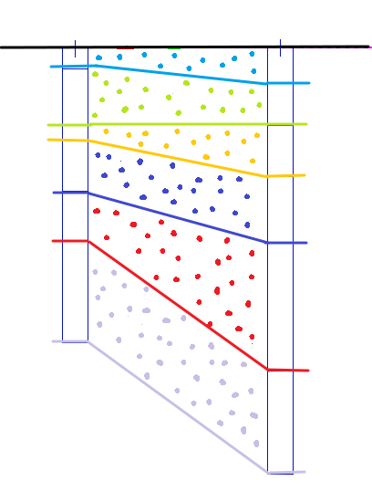
If there is some layer missing in one borehole, then it can be substituted by layer with minimum thickness – e.g. 1mm.o the soil-in has appropriate number of layers for approximation.
Foundation base
The level of the foundation base is considered on the bottom surface of the plate. The eccentricities are also taken into account.
Even the extrem example as this one place the foundation base to the bottom surface.
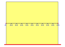
The red line indicates the foundation base.
Soil surface
Soil surface is a tool for initial approximation of subsoil surface and layers between boreholes.
Surface is calculated automatically according to inserted structure and inserted boreholes.
If it is deleted then it is automatically regenerated before the calculation starts.
Surface has its borders at least 10m outside the structure.
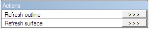
The surface is editable by 2 action buttons:
- Refresh outline: it recalculates the border
- Refresh surface: it recalculate the mesh of the surface
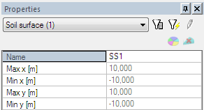
The properties of the surface are simple. Just a name and sizes:
It is possible to display deformed subsoil surface. It is created by several boreholes with different Z coordinates. The mesh is used only for displaying of terrain, it is not used for the calculation.
Surface support
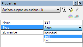
The surface support is basic structure object for soil-in. The support type is defined by combobox with 3 items.
Individual:
the C parameters are defined by user in the Subsoil manually (all of them). They are used for calculation. (e.g. contact stresses of the foundation surface)
Soilin:
system calculates C parameters (C1z, C2x, C2y) – this type is required for the complete soil-in calculation, C1x and C1y are taken from the solver setup
Both:
system calculates C1z, C2x and C2y if they are set to zero in the Subsoil; the rest is taken from the Subsoil. This item is used rarely only for a very special cases.
Soil-in type
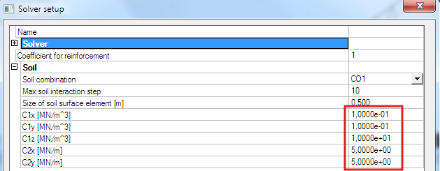
The only type which doesn’t use the data from the Subsoil library. All initial values of C parameters are defined by the Solver setup. C1x and C1y are taken from this setup as the results and the rest is calculated by the Soil-in.
The initial values could influence a bit the calculation convergence but their major importance is for setting of non-compressible stiffnesses. These values are 100 times higher than the initial values. That’s why a reduction of initial values (e.g. 10 times) can help in a convergence problems (higher depth, small loading, etc.)
Individual type
C1z, C2x, C2y parameters are taken from the Subsoil library. It is predefined by the user. The calculation of Soil-in won’t start in this case.
Both type
Soil-in calculates C1z, C2x and C2y only when they are set to the zero value by the user.
The parameters with any other value are taken from the library.
Example with type Both:
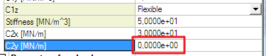
In this case the C2y parameter is calculated by soil-in. This item could be used only in a case when the soil-in would calculate any extreme values of C2 parameters. It is a very sporadic case.
The type Both is not too common and it was introduced mainly for two reasons:
First, I use type Soil-in but I want to have different friction in different parts of the structure. Therefore, the solver setup dialogue is not enough for me, because is just one value can be adjusted there for the friction. Therefore, I can use type Both and thus I am able to define several subsoils with non-zero constants C1x and C1y with all other parameters adjusted to zero. When the Soil-in module runs, the non-zero constants C1x and C1y are of higher priority than those determined by the solver and are applied. Other "zero" values indicate that the values determined by the solver are applied.
Second, sometimes it may be necessary to "suppress" higher values of shear (C2x, C2y) calculated by Soil-in module. This may happen e.g. when a new plate is modelled on an old one and the old plate is defined as the first layer of the subsoil. It is a correct and proper solution, but as E modules of soil and concrete are dramatically different, the Soil-in module calculates high C2 parameters. Consequently, the stiffness of the foundation slab in the model is bigger than if the two slabs were "joined" together and input as a homogenous monolith. Therefore, C2 parameters may be reduced artificially. This can be achieved in type Both. I define the subsoil with zero C1z (it will be determined by the Soil-in module) and other non-zero parameters (C2 and friction). Thus the Soil-in module will provide only for C1z parameter.
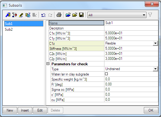
Subsoil library
The subsoil contains parameters which can be defined by the user or calculated by soil-in.
Parameters C1x and C1y are always defined by the user.