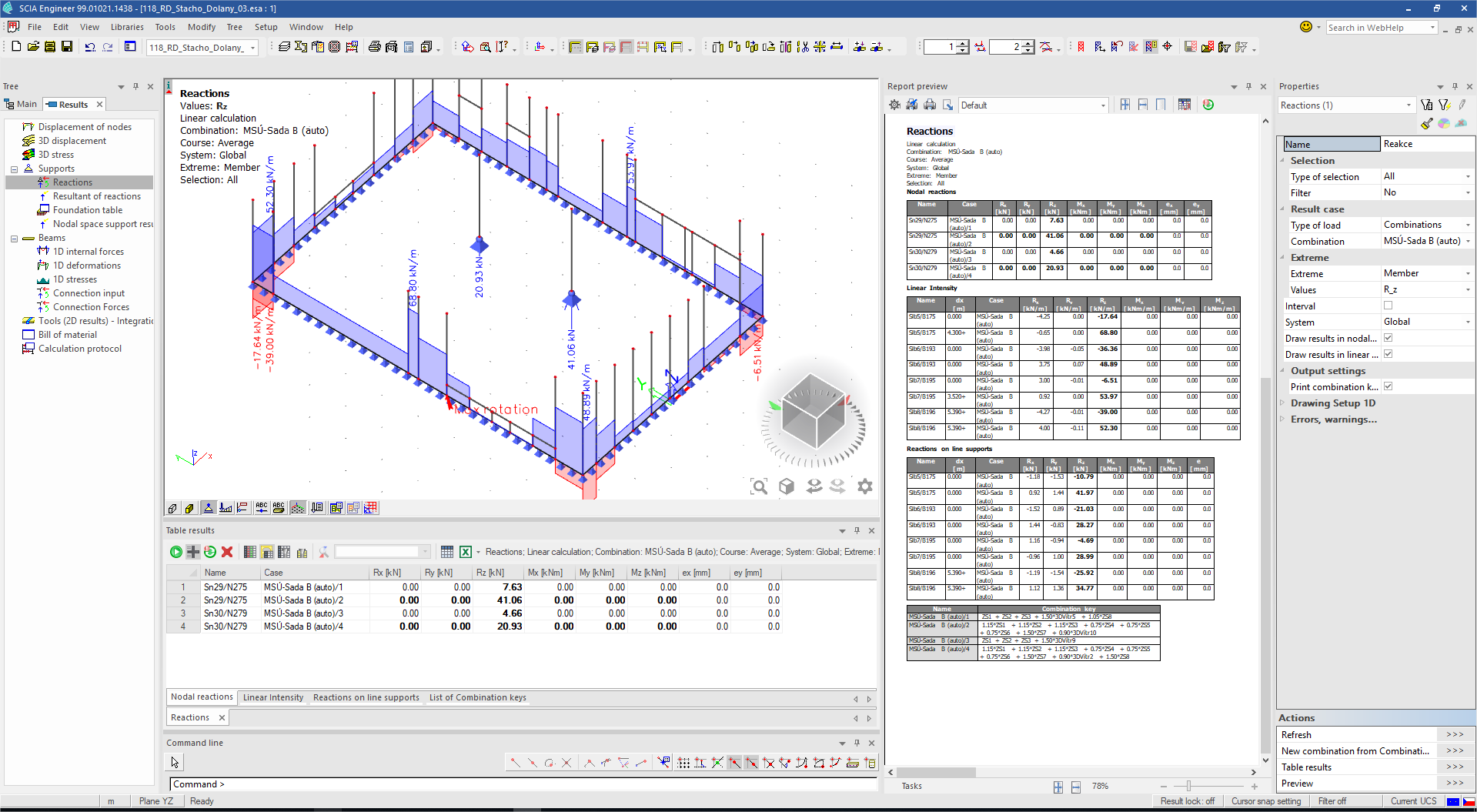
Reactions
The Reactions command serves for displaying nodal reactions and linear intensities on selected point or line supports in model.
Usage
- Calculate a FEM analysis of the model
- Go to Tree > Results > Supports > Reactions
- Set properties of the command to specify mainly:
- Click on [Refresh] action button to display the results
Note: To get general overview about how to work with Result service and its commands, see Results/Basics.
Properties
| Category | Property | Description / Notes |
|---|---|---|
| Selections |
Type of selection All / Current / Advanced / Named Selection / Design group
|
Specifies on what members the results are displayed
|
| Filter
No / Cross-section / Material / WildCard / Layer / Thickness / Type of beam / Pad foundation |
Specifies the filter of members on what the results are displayed See "Filter" |
|
| Result case | Type of load
Load case / Combinations / Classes / Nonlinear combinations / Mass combinations / Stability combinations |
Defines for what load the results are displayed. |
| Extreme | Extreme
No / Mesh / Member / Global |
Defines the position where extremes of result value are evaluated. note for "extreme no" option: If selected combination or class consist of too many linear combinations and thus it is not possible to display the results in full - conservative method that only displays results for linear combinations causing an extreme response of the structure is used instead. |
| Values
Rx / Ry / Rz / Mx / My / Mz / Components |
See table Values below. Components : possibility to choose more than one value and display them together in 3D window. Only selected values will be displayed in result tables. |
|
| Interval
On / Off |
Activation of interval of values for displaying in 3D window and in result tables. |
|
| Minimum [ ] | It is available only if Interval functionality is ON. User can define minimal value of interval. This item is unique for every type of unit used in Values. | |
| Maximum [ ] | It is available only if Interval functionality is ON. User can define maximal value of interval. This item is unique for every type of unit used in Values. | |
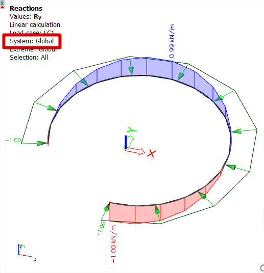
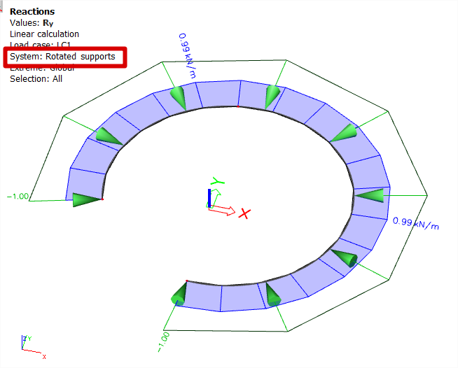
| System
Global / Rotated supports |
Sets a coordination system which is used as referenced for displaying the results.
|
|
| Draw results in nodal supports
On / Off |
Only results for nodal supports are displayed. | |
| Draw results in linear supports
On / Off |
Only results for linear supports are displayed. | |
| Output settings | Print combination key
On / Off |
|
| Display info about used interval
On / Off |
It is possible to display or not display in header of result tables information about applied intervals. | |
| Drawing Setup 1D | " Drawing setup 1D" | |
| Errors, warnings and notes settings | "Errors, warnings and notes settings" |
Values
| Value | Description | Notes |
|---|---|---|
| Rx | reaction in direction of local axis y |
1) The local axes can be displayed by selecting the corresponding option in the View parameters settings. |
| Ry | reaction in direction of local axis y | |
| Rz | reaction in direction of local axis z | |
| Mx | reaction around local axis x | |
| My | reaction around local axis y | |
| Mz | reaction around local axis z | |
| ex | eccentricity of reaction Mx / Rz | This items are displayed only in table for Engineering report. It is possible to hide them by switching values to components. |
| ey | eccentricity of reaction My / Rz | |
| Components | possibility to choose more than one value and display them together in 3D window. Only selected values will be displayed in result tables. |