Validation of modal analysis: relative modal masses
Dynamic analysis troubleshooting > modal analysis > protocol > relative modal masses
After a modal analysis, check the values of relative modal masses in the calculation protocol of eigen frequencies.
The table of relative masses gives valuable information about the overall behaviour of the structure.
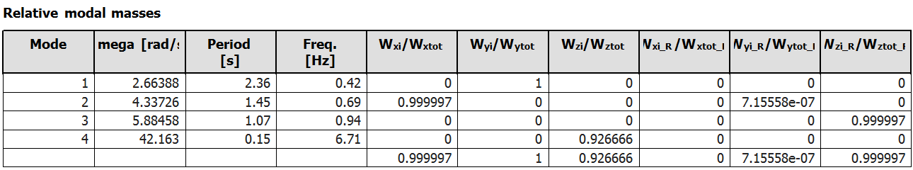
Mode
Mode shape order
Omega
Circular frequency of the mode in [rad/s]
Period
Period of the mode in [s]
Frequency
Frequency of the mode in [Hz]
Wxi/Wxtot, Wyi/Wytot, Wzi/Wztot
Relative modal mass in global direction X,Y,Z expressed as the ratio between the modal mass and the total mass in the same direction
Wxi_R/Wxtot_R, Wyi_R/Wytot_R, Wzi_R/Wztot_R
Relative modal mass inertia around the global axis X,Y,Z expressed as the ration between the modal inertia and the total inertia around the same axis
Relative modal masses (aka effective modal masses) are not the same as modal masses. For mode information about the specific definition of each of them, see the related theoretical background.
Relative modal masses are mostly used in the context of seismic analysis. The values Wxi/Wxtot and Wyi/Wytot are related to the value of the base shear. The other four components are evaluated in a similar way. Each of them gives an indication of how relevant a mode is for the seismic behaviour with regard to the corresponding seismic component.
| Relative modal mass component | Seismic component | |
| Wxi/Wxtot | horizontal seismic action in X direction | translational |
| Wyi/Wytot | horizontal seismic action in Y direction | |
| Wzi/Wztot | vertical seismic action | |
| Wxi_R/Wxtot_R | tilting around the X-axis | rotational |
| Wyi_R/Wytot_R | tilting around the Y-axis | |
| Wzi_R/Wztot_R | torsion around the Z-axis |
For seismic analysis, the modal participation factors are directly related to the relative modal masses. For other types of dynamic loading (harmonic, Von Karman, modal-based time-history), different calculations of the relative modal mass and modal participation factors are used.
Notes about relative modal masses in the context of seismic analysis
A brief analysis of the values listed in the table of relative modal masses can provide quickly a good overview of the seismic behaviour of a building. Several examples are presented below, starting with a typical, sound seismic behaviour. A few examples of less desirable behaviours are illustrated as well.
Typical regular structure
In a well designed - and well modelled! - structure, a sound seismic behaviour is typically reflected by the first few modes, as listed in the following example:
| Mode | Omega [rad/s] |
Period [s] |
Freq. [Hz] |
Wxi/ Wxtot |
Wyi/ Wytot |
Wzi/ Wztot |
Wxi_R/ Wxtot_R |
Wyi_R/ Wytot_R |
Wzi_R/ Wztot_R |
| 1 | 4.94535 | 1.27 | 0.79 | 0.0012 | 0.7149 | 0 | 0.1306 | 0.0022 | 0 |
| 2 | 7.61599 | 0.82 | 1.21 | 0.726 | 0.0012 | 0 | 0 | 0.0773 | 0 |
| 3 | 9.65372 | 0.65 | 1.54 | 0 | 0 | 0.0002 | 0 | 0 | 0.7134 |
| 4 | 23.34 | 0.27 | 3.71 | 0 | 0 | 0.677 | 0 | 0 | 0.0001 |
| 5 | 23.4055 | 0.27 | 3.73 | 0 | 0.0923 | 0 | 0.3025 | 0.1764 | 0 |
| 6 | 23.8588 | 0.26 | 3.8 | 0.0005 | 0.1032 | 0 | 0.0048 | 0.0713 | 0 |
| 7 | 27.9093 | 0.23 | 4.44 | 0 | 0.0006 | 0 | 0.0099 | 0.0163 | 0 |
| 8 | 28.3399 | 0.22 | 4.51 | 0 | 0.0001 | 0 | 0.0033 | 0.0037 | 0 |
| 9 | 28.451 | 0.22 | 4.53 | 0 | 0 | 0 | 0.0007 | 0.0008 | 0 |
| 10 | 31.5033 | 0.2 | 5.01 | 0.1642 | 0.0001 | 0 | 0.0543 | 0.0299 | 0 |
| 11 | 32.1974 | 0.2 | 5.12 | 0 | 0 | 0.0573 | 0 | 0 | 0 |
| 12 | 33.2494 | 0.19 | 5.29 | 0 | 0 | 0.0121 | 0 | 0 | 0 |
| 13 | 33.3891 | 0.19 | 5.31 | 0.0454 | 0.0019 | 0 | 0.155 | 0.2788 | 0 |
| 14 | 33.508 | 0.19 | 5.33 | 0 | 0 | 0.0022 | 0 | 0 | 0 |
| 15 | 36.867 | 0.17 | 5.87 | 0.0003 | 0.0032 | 0 | 0.0005 | 0.0085 | 0 |
| 0.9375 | 0.9174 | 0.7489 | 0.6614 | 0.6652 | 0.7135 |
- the first two modes exhibit a high relative modal mass in direction X and Y and little or zero in rotation around the Z-axis
- in higher frequencies (here in position 3), there is one or more modes with high torsional participation
- in higher frequencies (here in position 4), there is one of more modes with high vertical participation
- the sum of relative modal masses in direction X and Y reaches 90% with a reasonable number of modes; for the vertical component, it is not uncommon that a larger number of modes is required to reach 90%, however, it is often not necessary to consider the vertical component in the modal analysis (a static equivalent approach is often sufficient)
This example is almost academic, since such nicely regular and symmetrical structures are very seldom in reality. However, the fundamental translational modes should always appear at the top of the list.
Torsional mode in first position
The presence of a purely torsional mode at the top of the list is the sign of a shear wall system with low eccentricity, but also an insufficient torsional stiffness. It means, that accidental eccentricity effects could have a serious impact on the structure.
| Mode | Omega [rad/s] |
Period [s] |
Freq. [Hz] |
Wxi/ Wxtot |
Wyi/ Wytot |
Wzi/ Wztot |
Wxi_R/ Wxtot_R |
Wyi_R/ Wytot_R |
Wzi_R/ Wztot_R |
| 1 | 0.745 | 8.43 | 0.12 | 0.0062 | 0.0034 | 0 | 0.0007 | 0.0006 | 0.7729 |
| 2 | 1.759 | 3.57 | 0.28 | 0.0008 | 0.0002 | 0 | 0.0052 | 0.0001 | 0.1504 |
| 3 | 2.291 | 2.74 | 0.36 | 0.0006 | 0.0014 | 0 | 0.0009 | 0.0002 | 0.0565 |
| 4 | 2.548 | 2.47 | 0.41 | 0 | 0.0001 | 0 | 0.0005 | 0 | 0.0093 |
| 5 | 3.668 | 1.71 | 0.58 | 0.3884 | 0.3448 | 0.0001 | 0.0744 | 0.0522 | 0.0009 |
| 6 | 3.755 | 1.67 | 0.6 | 0.3294 | 0.393 | 0.0002 | 0.084 | 0.0488 | 0.0066 |
| ... | ... | ... | ... | ... | ... | ... | ... | ... | ... |
Significant torsional component in fundamental modes
When fundamental modes exhibit significant values in both translational and torsional components, it is a sign of a significant eccentricity in the shear wall system.
| Mode | Omega [rad/s] |
Period [s] |
Freq. [Hz] |
Wxi/ Wxtot |
Wyi/ Wytot |
Wzi/ Wztot |
Wxi_R/ Wxtot_R |
Wyi_R/ Wytot_R |
Wzi_R/ Wztot_R |
| 1 | 0.57416 | 10.94 | 0.09 | 0.2404 | 0.3052 | 0 | 0.048 | 0.0249 | 0.234 |
| 2 | 2.09294 | 3 | 0.33 | 0.0339 | 0.0729 | 0 | 0.1097 | 0.0602 | 0.0465 |
| 3 | 4.22765 | 1.49 | 0.67 | 0.2703 | 0.3971 | 0.0007 | 0.086 | 0.0224 | 0.0521 |
| 4 | 4.38956 | 1.43 | 0.7 | 0.0099 | 0.0287 | 0 | 0.0331 | 0.0164 | 0.0166 |
| ... | ... | ... | ... | ... | ... | ... | ... | ... | ... |
Insignificant modes
Modes with small values for all modal mass components might appear in the table. There are essentially two types of modes that can exhibit such modal mass values:
- local modes, where only a very small portion of the structure is in vibration
- high-order overall modes, where positive and negative displacement values compensate each other and result in very small modal mass values; it is, however, seldom, that all 6 mass components are small at the same time for such modes
In most cases, modes with small translational modal mass components are irrelevant for the overall seismic behaviour of the structure and, therefore, can be simply ignored.
However, when such modes appear at the top or near the top of the list, with very low frequency values, it is often a sign, that some part of the model is exaggeratedly flexible. In theory, it is not an issue for the seismic analysis. However, it can increase significantly the number of required modes to achieve a sufficient precision (90% modal mass condition). This affects the computation time and, in extreme cases, can cause numerical convergence issues. It is therefore recommended to avoid those modes, if possible. Some typical cases:
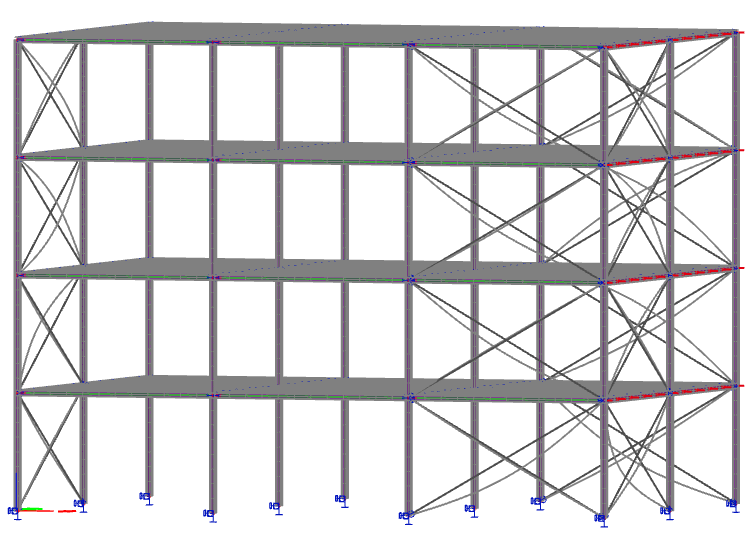
Unbraced beams
Composite decks and metal decks are commonly modelized by a grid of beams combined with a load panel to apply the surface loads to the system. In such a case, the beams are connected to each other only at their ends and, taken individually, are quite flexible. They might have a quite low local fundamental frequency. Moreover, small differences of span length, cross-section and loading can induce a large number of slightly different frequencies and associated modes. Such modes, although they have a small modal mass, are not insignificant and must be considered in the seismic modal superposition.
However, independent vibrations of those beams are not realistic. In reality, the deck connects the beams together along their entire length. A more appropriate approach consists of taking that connection into account by using a diaphragm rather than a load panel, which simply eliminates the local modes.
Diagonals
Bracing diagonals are typically very slender 1D members. As they are meant to act essentially in tension, they hardly have any bending stiffness and are therefore prone to exhibit local vibration modes, which are totally irrelevant for the overall behaviour of a building. A very simple way of avoiding such local modes consists of using axial force only members for diagonals.
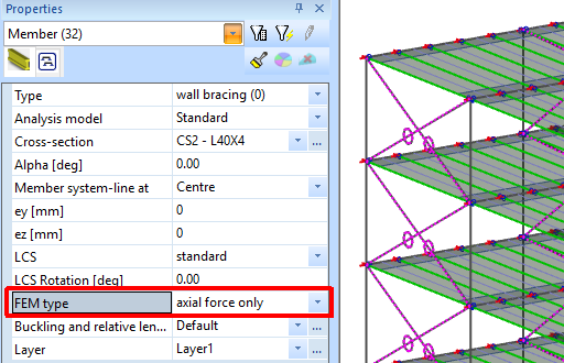
SCIA Engineer avoids automatically mesh refinement on axial force only members. It means, that they have no intermediate node. Their mass is concentrated on their end nodes, which eliminates the possibility of local modes on such members.
Cables
Cables are similar to diagonals, in that they have no bending stiffness and act only in tension. However, they are usually pre-tensioned, which gives them an apparent quite high transversal stiffness and, in reality, a high fundamental frequency (like a guitar string). The pre-tensioning, however, is not taken into account by default in the dynamic analysis, which can lead to very low frequencies on cable members.
Two solutions to avoid it:
- in the same way as for diagonals, use axial force only members
- take the pre-tensioning of the cables into account in the dynamic analysis using initial stresses
Non-seismic members
Non seismic members, aka secondary members, can be a source of unwanted local modes. Because such members are not meant to participate in the shear resisting system, they are usually modelled with a low stiffness value or weak connection to the rest of the structure. In both cases, that makes such members very flexible and, therefore, likely to exhibit local modes at quite low frequencies.
Ideally, non-seismic members should not be included in the analysis model as structural parts. If, for some reason, they have to be included in the analysis model, consider moving their mass to the closest primary member. For instance, for a non-seismic masonry wall, set its mass density to zero using property modifiers and add an equivalent line mass along the bottom edge of the wall. As a simplification, the mass of non-seismic walls may also be distributed as a surface mass on their supporting slab.
High-order mode shapes
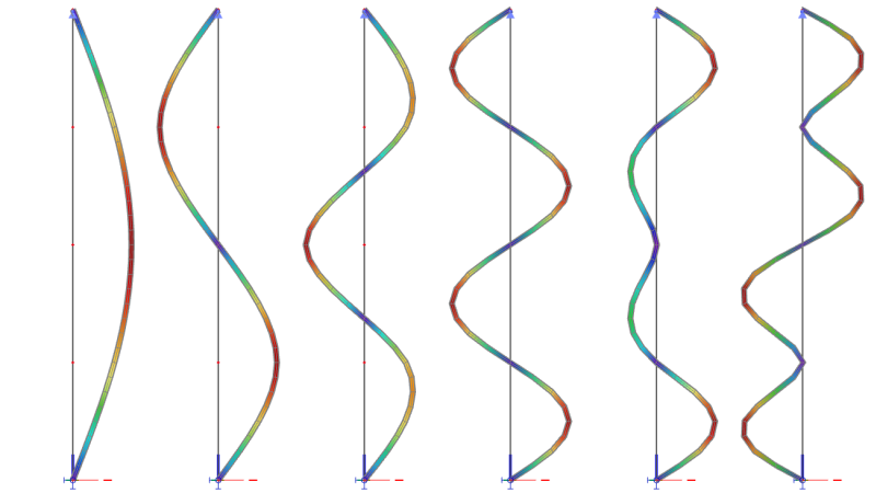
Strictly speaking, any mode that is not a fundamental mode is a high-order mode.Typically, considering the possible modes of a beam or a column, a fundamental mode - aka first order mode - has no inflexion point. A second order mode has one inflexion point, a third order mode has two inflexion point, and so on... For instance, consider a column with hinged supports at both ends and 3 masses located at 1/4, 1/2 and 3/4 of its length, plus its self mass. The first 6 mode shapes are as shown in the following picture.
| Mode | Freq. [Hz] |
Wxi/ Wxtot |
Remarks |
| 1 | 0.34 | 0.9690 | 1st order, no inflexion point, fundamental mode; all displacements have the same sign, most of the relative modal mass is taken |
| 2 | 1.34 | 0 | 2nd order, 1 inflexion point; perfectly antimetric, the relative modal mass is exactly zero |
| 3 | 2.81 | 0.0292 | 3rd order, 2 inflexion points; opposed signs do not compensate each other exactly; the relative modal mass is low, but non-zero |
| 4 | 41.09 | 0 | 4th order, 3 inflexion points; perfectly antimetric, the relative modal mass is exactly zero |
| 5 | 47.41 | 0.0013 | 5th order, 4 inflexion points; opposed signs do not compensate each other exactly; the relative modal mass is low, but non-zero |
| 6 | 62.03 | 0 | 6th order, 5 inflexion points; perfectly antimetric, the relative modal mass is exactly zero |
Final remarks
Reviewing the summary table of relative modal masses can give a good overview of the overall seismic behaviour of a building.
- High values of relative modal mass should be at the beginning of the list, primarily for translational components
- High values for rotational components should come second
- The presence of modes with low values for all components is most a sign of flexible parts in the mode, which are probably not relevant for the seismic behaviour; such modes must be reviewed and, if possible, eliminated by adjusting the model
See more details about the evaluation of modes in the next chapter.
Next step: evaluation of mode shapes