Validation of modal analysis: mode shapes
Dynamic analysis troubleshooting > modal analysis > mode shapes
After a modal analysis, another essential step is the evaluation of the shape of the fundamental modes. This includes modes with high relative modal mass, but also modes with a low relative modal mass and a low frequency. As already mentioned, such modes should not be present at the top of the list.
Also, suspicious modes identified in the relative modal mass summary should be reviewed.
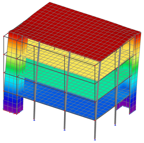
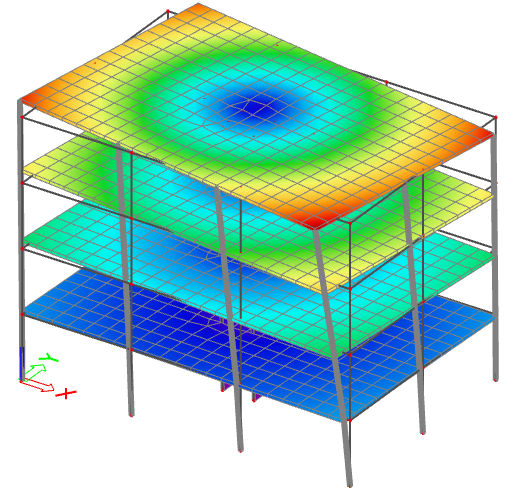
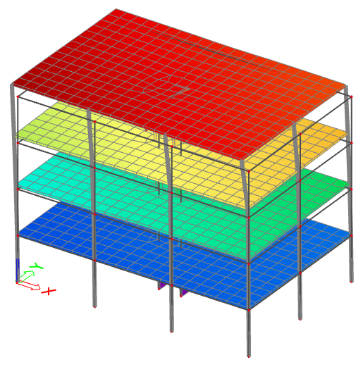
Regular system
This is a typical regular system, almost academic. The obtained results are what is typically expected for a well designed building.
| Mode | Omega [rad/s] |
Period [s] |
Freq. [Hz] |
Wxi/ Wxtot |
Wyi/ Wytot |
Wzi/ Wztot |
Wxi_R/ Wxtot_R |
Wyi_R/ Wytot_R |
Wzi_R/ Wztot_R |
| 1 | 4.94535 | 1.27 | 0.79 | 0.0012 | 0.7149 | 0 | 0.1306 | 0.0022 | 0 |
| 2 | 7.61599 | 0.82 | 1.21 | 0.726 | 0.0012 | 0 | 0 | 0.0773 | 0 |
| 3 | 9.65372 | 0.65 | 1.54 | 0 | 0 | 0.0002 | 0 | 0 | 0.7134 |
| 4 | 23.34 | 0.27 | 3.71 | 0 | 0 | 0.677 | 0 | 0 | 0.0001 |
| ... | ... | ... | ... | ... | ... | ... | ... | ... | ... |
- the first two modes exhibit a high relative modal mass in direction X and Y and little or zero in rotation around the Z-axis
- in higher frequencies (here in position 3), there is one or more modes with high torsional participation
- in higher frequencies (here in position 4), there is one of more modes with high vertical participation
- the sum of relative modal masses in direction X and Y reaches 90% with a reasonable number of modes; for the vertical component, it is not uncommon that a larger number of modes is required to reach 90%, however, it is often not necessary to consider the vertical component in the modal analysis (a static equivalent approach is often sufficient)
The corresponding mode shapes are shown below:
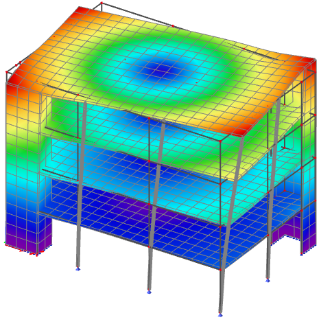
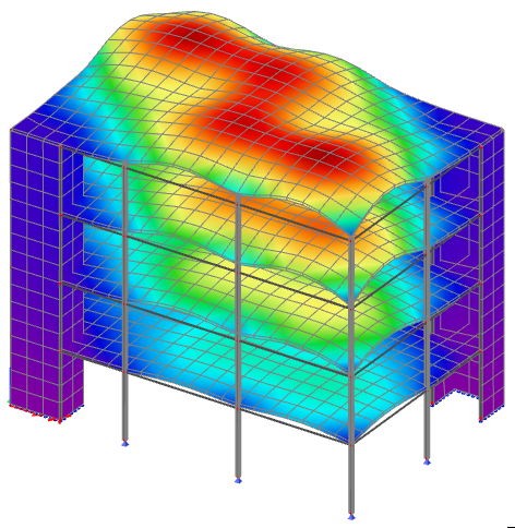
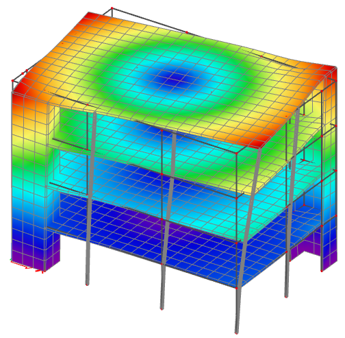
As an example, here is the mode shape of the 100-th mode at 21.3 Hz, which is a typical high-order vertical mode (bending in the slabs), which can also be seen as a superposition of multiple local modes. Such mode has an extremely low relative modal mass and is irrelevant for the overall seismic behaviour.
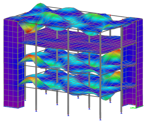
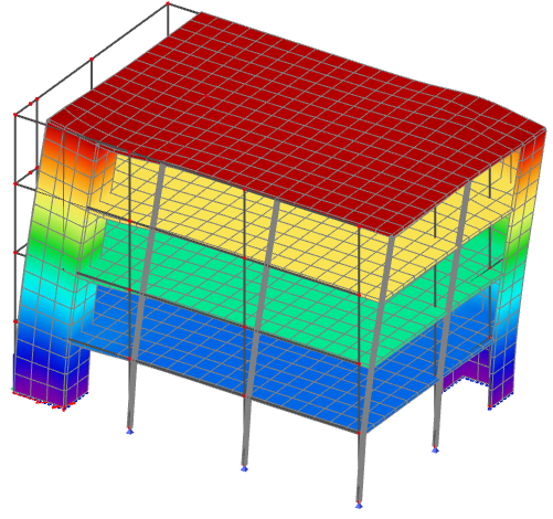
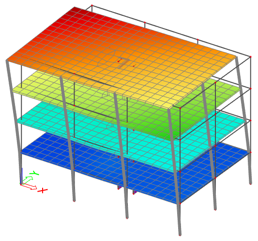
Weak system in torsion
The presence of a purely torsional mode at the top of the list is the sign of a shear wall system with low eccentricity, but also an insufficient torsional stiffness. It means, that accidental eccentricity effects could have a serious impact on the structure.
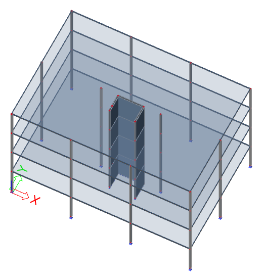
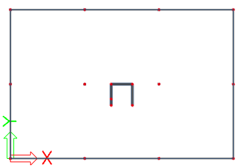
In this case, the shear resisting system is made of a single core in the middle of the building.
| Mode | Omega [rad/s] |
Period [s] |
Freq. [Hz] |
Wxi/ Wxtot |
Wyi/ Wytot |
Wzi/ Wztot |
Wxi_R/ Wxtot_R |
Wyi_R/ Wytot_R |
Wzi_R/ Wztot_R |
| 1 | 0.745 | 8.43 | 0.12 | 0.0062 | 0.0034 | 0 | 0.0007 | 0.0006 | 0.7729 |
| 2 | 1.759 | 3.57 | 0.28 | 0.0008 | 0.0002 | 0 | 0.0052 | 0.0001 | 0.1504 |
| 3 | 2.291 | 2.74 | 0.36 | 0.0006 | 0.0014 | 0 | 0.0009 | 0.0002 | 0.0565 |
| 4 | 2.548 | 2.47 | 0.41 | 0 | 0.0001 | 0 | 0.0005 | 0 | 0.0093 |
| 5 | 3.668 | 1.71 | 0.58 | 0.3884 | 0.3448 | 0.0001 | 0.0744 | 0.0522 | 0.0009 |
| 6 | 3.755 | 1.67 | 0.6 | 0.3294 | 0.393 | 0.0002 | 0.084 | 0.0488 | 0.0066 |
| ... | ... | ... | ... | ... | ... | ... | ... | ... | ... |
From the relative modal mass values, the first two modes are clearly pure torsional modes, as only the Wzi_R component shows significant values. The 4-th mode is less obvious, but the mode shapes of the first 4 modes clearly show pure torsional behaviour, with 1st, 2nd, 3rd and 4th order torsional modes.
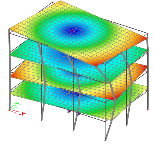
Modes 5 and 6 show an interesting discrepancy. As the geometry of the building has a symmetry plane in the Y direction, and the U-shaped core is almost centred, the fundamental translational modes would be expected in direction X and Y. Modes 5 and 6 would be expected to have a high value of relative modal mass in the X (resp. Y) direction and zero in the perpendicular direction, which is not the case. Because the stiffness of the core is almost the same in X and Y directions, the slight irregularity of the mesh near the core (visible on the provided pictures) causes the principal axes of the system to rotate by almost 45°, leading to 2 modes with coupled behaviour in directions X and Y.
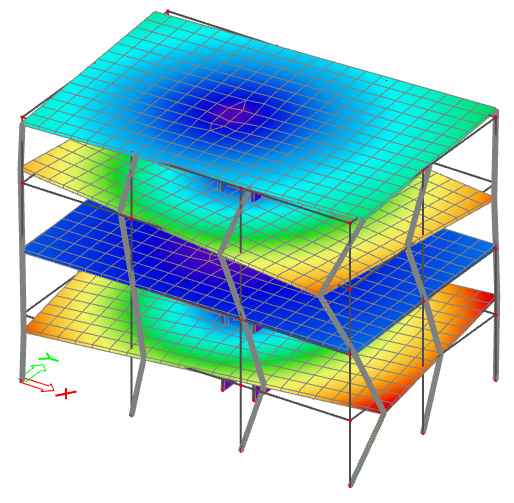
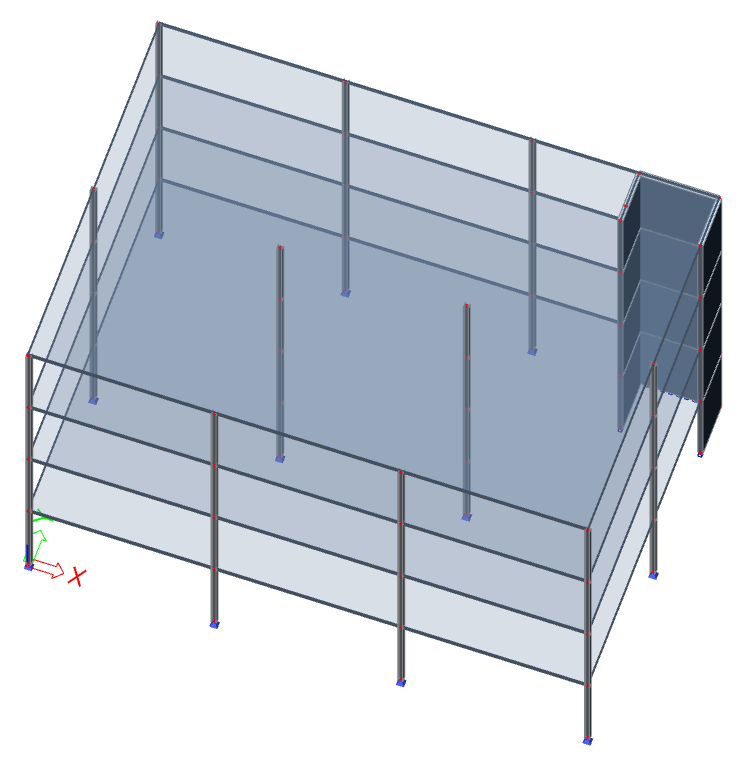
Eccentric shear wall system
In case of a shear resisting system with strong eccentricity, modes with combined significant participation in both translation directions and torsion appear simultaneously.
| Mode | Omega [rad/s] |
Period [s] |
Freq. [Hz] |
Wxi/ Wxtot |
Wyi/ Wytot |
Wzi/ Wztot |
Wxi_R/ Wxtot_R |
Wyi_R/ Wytot_R |
Wzi_R/ Wztot_R |
| 1 | 0.57416 | 10.94 | 0.09 | 0.2404 | 0.3052 | 0 | 0.048 | 0.0249 | 0.234 |
| 2 | 2.09294 | 3 | 0.33 | 0.0339 | 0.0729 | 0 | 0.1097 | 0.0602 | 0.0465 |
| 3 | 4.22765 | 1.49 | 0.67 | 0.2703 | 0.3971 | 0.0007 | 0.086 | 0.0224 | 0.0521 |
| 4 | 4.38956 | 1.43 | 0.7 | 0.0099 | 0.0287 | 0 | 0.0331 | 0.0164 | 0.0166 |
| ... | ... | ... | ... | ... | ... | ... | ... | ... | ... |
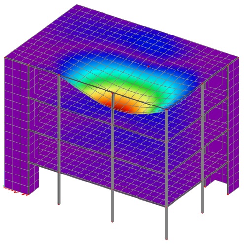
In this case, the first mode has a significant modal mass in direction Y, combined with also significant values for direction X and rotation around the Z-axis. That is symptomatic of a strong asymmetry of the structure and eccentricity of the shear wall system. The mode shape clearly shows the combined translation and rotations components.
The second mode has non-zero but fairly low values for all translational and torsional components. It is a typical second order mode, where positive and negative values compensate each other.
The third mode has again significant values for both translational components X and Y, but a lower torsional component than mode 1. Given the geometry of the structure, it is the logical secondary fundamental mode, roughly orthogonal to mode 1.


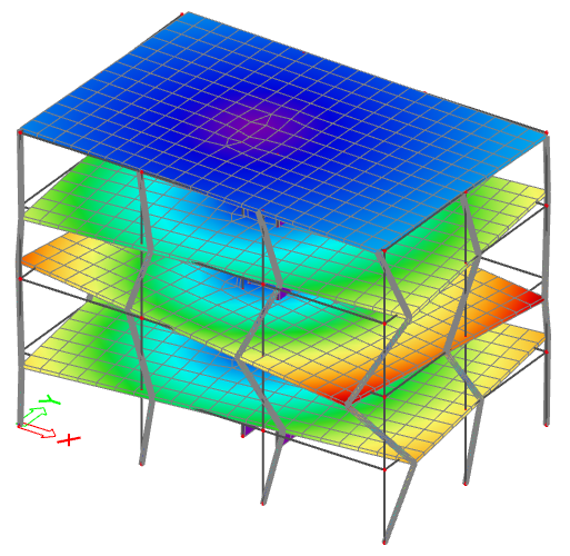
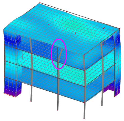
Symmetric building with connection fault
This example is the same as the first regular system example, except for the fact, that one of the columns of the top floor is not connected to the roof slab. That causes a number of disruptions that are visible both in the calculation protocol and in the mode shapes.
First, considering the relative modal masses:
- Modes 1 & 2 are typical, predominant translation modes; no problem visible there
- Mode 3 is a typical torsional fundamental mode; again, no problem visible here, as such a mode in 3rd position is quite common
- Mode 4 is a vertical mode. Nothing strange in itself, but it is immediately followed by another vertical mode with a much higher participation value. As the structure is symmetrical and regular, the first vertical mode should have the higher value.
- Mode 5 has a high vertical participation value, combined with significant rotational components around X and Y axes. This is a sign of an eccentric vertical participation which, again, as the structure is symmetrical and regular, should not happen. Actually, looking back at mode 4, a similar behaviour is visible there, just with smaller values for the rotational components.
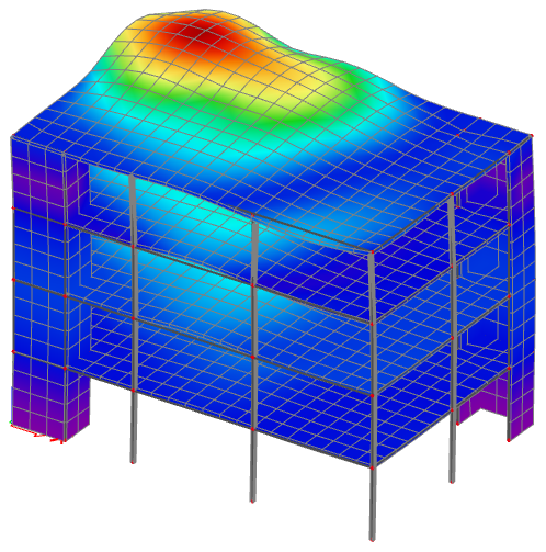
- Mode 6 shows combined significant translational values in directions Y and Z and rotational value around the X-axis. This is typical of a cantilever in the direction Y. But the structure has no cantilever...
| Mode | Omega [rad/s] |
Period [s] |
Freq. [Hz] |
Wxi/ Wxtot |
Wyi/ Wytot |
Wzi/ Wztot |
Wxi_R/ Wxtot_R |
Wyi_R/ Wytot_R |
Wzi_R/ Wztot_R |
| 1 | 4.945 | 1.27 | 0.79 | 0.0012 | 0.7149 | 0 | 0.1303 | 0.0022 | 0 |
| 2 | 7.616 | 0.82 | 1.21 | 0.7259 | 0.0012 | 0 | 0 | 0.077 | 0 |
| 3 | 9.654 | 0.65 | 1.54 | 0 | 0 | 0.0002 | 0 | 0 | 0.7133 |
| 4 | 14.86 | 0.42 | 2.37 | 0 | 0 | 0.0771 | 0.0368 | 0.0209 | 0 |
| 5 | 23.117 | 0.27 | 3.68 | 0 | 0.0109 | 0.3629 | 0.0979 | 0.0955 | 0 |
| 6 | 23.593 | 0.27 | 3.75 | 0.0001 | 0.1738 | 0.0556 | 0.1595 | 0.0112 | 0 |
| ... | ... | ... | ... | ... | ... | ... | ... | ... | ... |
Keeping the observations above in mind, let's look at the corresponding modal shapes.
As previously noted, modes 1, 2 and 3 are typical fundamental modes in translation and torsion. Slight discrepancies are visible in modes 1 and 2 when looking closely. In a larger, more complex model, this would certainly go unnoticed. In mode 3, the discrepancy is not visible.
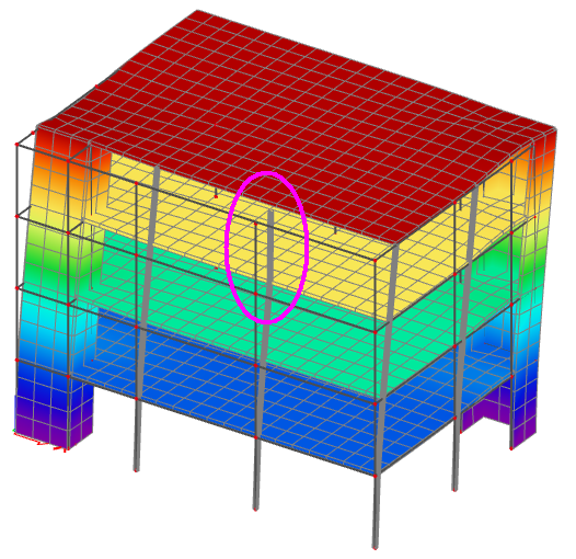
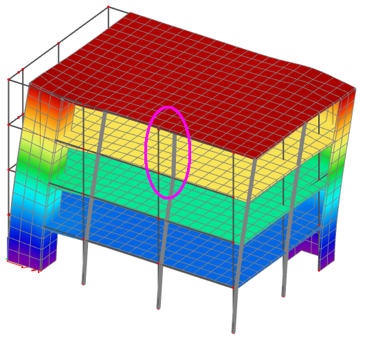
In mode 4 appears the small vertical participation, due to the disconnected column. The roof slab exhibits a large deflection. Because that deflection is largely eccentric compared to the mass centre of the structure, the rotational components are non-zero. The deformed shape shows clearly the disconnected column.
In mode 5, the vertical participation appears on the opposite side of the structure. That is the counterpart of mode 4. If the column would have been connected, modes 4 and 5 would have been "combined", resulting in the mode 4 obtained in the very first example at the beginning of this chapter (regular system).
In mode 6, again, the disconnected column is clearly visible. Although it is not obvious on the deformed shape, the disconnected column causes a significant asymmetry in directions Y and Z, which is visible in the relative modal masses.
Next step: specific checks for seismic analysis