Summary Storey Results
This service provides results directly produced by the IRS analysis (see Reduced analysis model ). At this time, this service is dedicated to result output for the seismic analysis of buildings. It provides single results per storey, such as mass, position of mass center, displacement, acceleration…
Pre-requisites for using Summary Storey Results:
- storeys must be defined
- the reduced analysis model must be enabled in the solver settings
The service may be found in the Results service. It is available only after a successful dynamic analysis using the reduced model.
Output Settings
The output settings are presented here according to the various types of results that can be obtained from this service. There are 4 types of results:
- Storey Data: information of the reduced analysis model, such as the mass and the position of the mass center of each storey
- Displacements: displacements at the mass center of each storey
- Accelerations: accelerations at the mass center of each storey
- Inter-storey drift: relative displacements at the mass center of each storey, relative to the storey immediately below
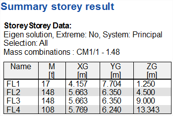
Result type Storey Data
For mass combinations, it displays for each storey the total mass and the coordinates of the mass center.
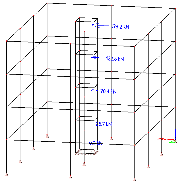
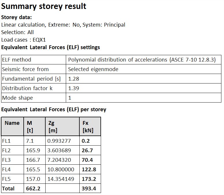
For ELF seismic load cases, summary information about computed storey forces is displayed.
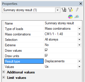
Type of loads
Mass combinations
selection of the combination of mass groups or eigenmode for a given combination of mass groups.
Selection
type of selection; the possible choices are
- All storeys
- Named selection
- Single storey
Named selection
named selection that contains a set of storeys; only if Selection = Named selection
Storey
dropdown menu for selection of a single one; only if Selection = Single storey
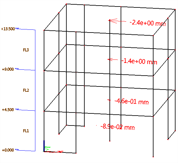
Draw values
tick to draw values on the drawing
tick to draw values with their units on the drawing
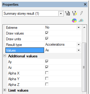
Result type
types of results; possible choices are
- Displacements
- Inter-storey drift
- Accelerations
- Storey Data
Values
main component to be displayed; only when an ELF seismic load case is selected
Fx, Fy, Fz : components of the seismic storey forces
Ftot : resultant seismic force per storey
M : mass of each storey
Additional values
allow to show more than one result component simultaneously on the drawing.
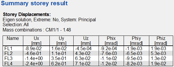
Content of the output table for mass combinations
In the case of storey data output for a mass combination, the following columns are displayed in the preview and table output, for each storey:
M: mass of each storey, taken as the max value of Mxx, Myy and Mzz
XG, YG, ZG: GCS-coordinates of the mass center of each storey
Mxx, Myy, Mzz: mass components of each storey, in X, Y, Z direction of the GCS


Ixx, Iyy, Izz: mass inertia components of each storey, around X, Y, Z axes of the GCS


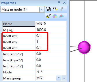
In common cases, M = Mxx = Myy = Mzz. However, they may differ in the following cases:
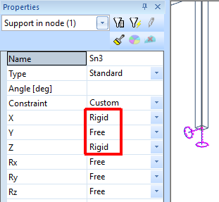
- non-isotropic boundary conditions: rigid supports with different properties in X, Y and Z direction and the supported structural entity has non-zero mass
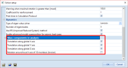
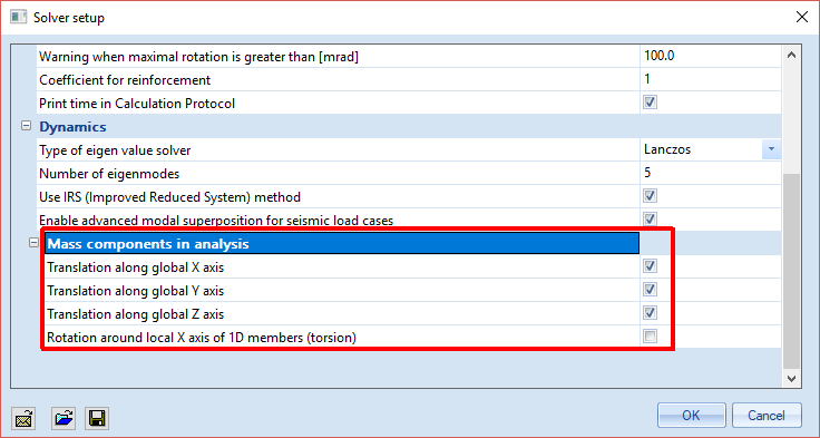
- use of mass direction components (see Dynamics section in the solver setup)
- use of directional mass coefficients in mass definition
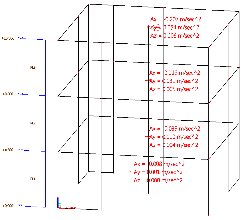
Result types Displacements, Accelerations & Inter-storey drift
Displacements & Accelerations are available for eigenmodes and dynamic seismic load cases. The values of displacement & acceleration components are given at the mass center of each storey. Thsi also applies to inter-storey drift results.
Results for mass combinations are raw, normalized results from modal analysis, without effect of response spectrum.
Results for seismic load cases are values after modal superposition.
Displacement, acceleration and inter-storey drift summary storey results are not supported for ELF load cases.
Type of loads
selection of the type of load
- Mass combinations
- Load cases
Mass combination
list of available eigenmodes for each computed combination of mass groups; only if Type of loads = Mass combinations
Load cases
list of available seismic load cases; only if Type of loads = Load cases
Selection
type of selection; the possible choices are
- All storeys
- Named selection
- Single storey
Named selection
named selection that contains a set of storeys; only if Selection = Named selection
Storey
dropdown menu for selection of a single one; only if Selection = Single storey
Extreme
filter extreme results; possible choices are
- No
- Section (relevant only for seismic load cases)
- Member (relevant only for seismic load cases)
- Global
Draw values
tick to draw values on the drawing
Draw units
tick to draw values with their units on the drawing
Result type
types of results; possible choices are
- Displacements
- Inter-storey drift
- Accelerations
- Storey Data
Values
main component to be displayed;
for Result type = Displacements
u_x, u_y, u_z : displacement at mass center according to GCS axes
φ_x, φ_y, φ_z : rotation at mass center around GCS axes
for Result type = Inter-storey drift
Δux, Δuy, Δuz : relative displacement at mass center according to GCS axes, relative to the storey immediately below
Δφ_x, Δφ_y, Δφ_z : relative rotation at mass center around GCS axes, relative to the storey immediately below
for Result type = Accelerations
Ax, Ay, Az : acceleration at mass center according to GCS axes
AlphaX, AlphaY, AlphaZ : rotational acceleration at mass center around GCS axes
Additional values
allow to show more than one result component simultaneously on the drawing.
When only the main component is selected (no additional value ticked), the selected component is drawn in the corresponding direction.
When one or more additional value is ticked, all selected components are listed in the plane of the screen for better readability.
Limit values
for each result component, definition of min and max value for colour coding on the drawing. Colours may be configured in Settings > Colours/Lines.
Default colour coding is as follows:
Values lower than Vmin are display in red
Values between Vmin and Vmax are displayed in gray
Values greater than Vmax are displayed in blue