Detailed Storey Results
This service provides results from the full mesh analysis. It may be used for results from any linear analysis, with or without dynamic analysis, with or without IRS analysis. It provides results in all supporting members, with easy selection of members per storey. Walls and columns may be represented on the same drawing.
Typical provided results are: internal forces, resultant forces per wall or per storey…
Pre-requisites for using Summary Storey Results:
- storeys must be defined
- supporting members must be properly allocated to storeys
Before using detailed storey results, make sure that all supporting members of the building are properly allocated to storeys. That information is essential for proper handling of storey results.
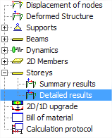
The service may be found in the Results service. It is available only after a successful analysis, if storeys are defined.
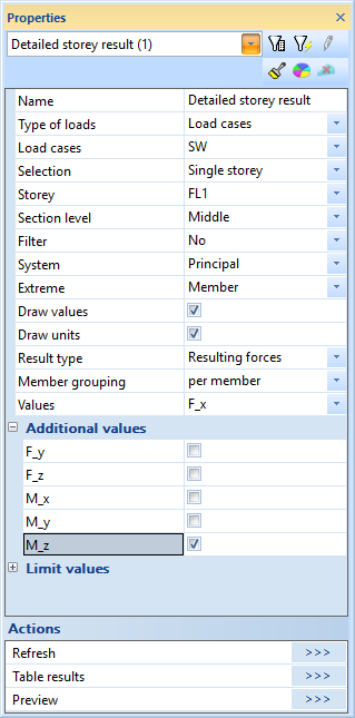
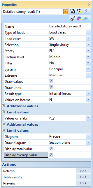
Output Settings
Mainly 2 types of results are available in this service:
- Internal forces in supporting members
- Resulting forces
For resulting forces, the Member grouping may be selected:
- per member: compute the resulting forces for each supporting member separately
- per storey: compute the resulting forces for each entire storey at once, combining 1D and 2D members
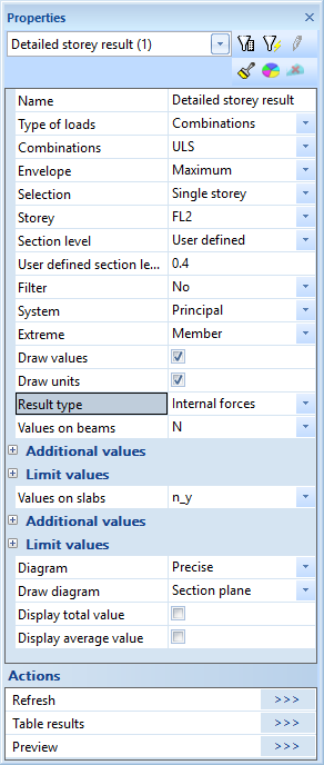
Result type Internal forces
Type of loads
selection of the type of load
- Load cases
- Combinations
- Class
Load cases
list of available load cases; only if Type of loads = Load cases
Combinations
list available load case combinations; only if Type of loads = Combinations
Class
list of available result classes; only if Type of loads = Class
Envelope
Maximum / Minimum; select the maximum or minimum value of an envelope; only if Type of loads = Combinations or Class
Selection
type of selection; the possible choices are
- All storeys
- Named selection
- Single storey
Named selection
named selection that contains a set of storeys; only if Selection = Named selection
Storey
dropdown menu for selection of a single storey; only if Selection = Single storey
Section level
level where the section must be made across the supporting members in each storey; possible choices:
- Top (section at the top of each storey)
- Middle (section at mid-height of the each storey)
- Bottom (section at the bottom of each storey)
- User defined
User defined section level
level of section in each storey; 0 = bottom of the storey, 1 = top of the storey
Filter
filtering of supporting members for the output; possible choices are
- No
- Wildcard
- Material
- Thickness / CSS
- Layer
Wildcard
wildcard for name filtering of members; only if Filter = Wildcard
Material
list of available materials for material filtering of members; only if Filter = Material
Thickness
value of thickness for thickness filtering of members; only if Filter = Thickness/CSS; 0 = all thickness values
CSS
list of available cross-sections for filtering of members; only if Filter = Thickness/CSS
Layer
list of available layers for filtering of members; only if Filter = Layer
System
selection of coordinate system for output of internal forces in 1D members; possible choices are
- principal (principal axes of the cross-section)
- LCS (LCS of the 1D member)
for 2D members, the LCS is always used
Extreme
filter extreme results; possible choices are
- No
- Section
- Member
- Global
Draw values
tick to draw values on the drawing
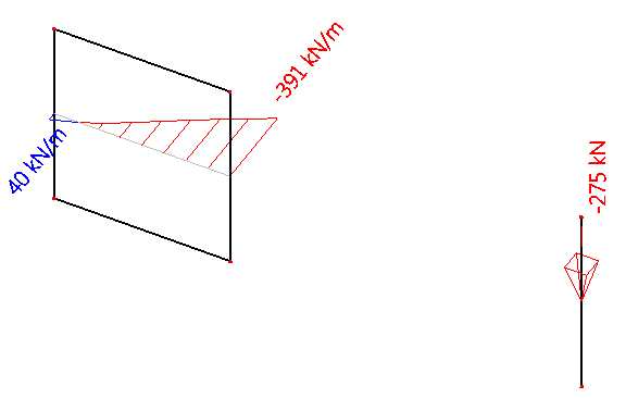
tick to draw values with their units on the drawing
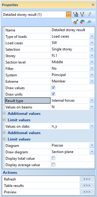
Result type
selection of result type; possible choices are
- internal forces
- resulting forces
Values on beams
main component to be displayed on 1D members (columns); possible choices are
- N = axial force
- Vy = shear force according to Y-axis of selected system
- Vz = shear force according to Z-axis of selected system
- Mx = torsional moment
- My = bending moment around the Y-axis of selected system
- Mz = bending moment around the Z-axis of selected system
Additional values
allow to show more than one result component simultaneously on the drawing for 1D members; possible choices: see Values on beams
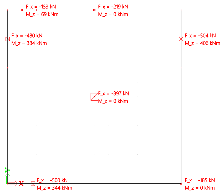
When only the main component is selected (no additional value ticked), the selected component is drawn in the corresponding direction.
When one or more additional value is ticked, all selected components are listed in the plane of the screen for better readability.
Limit values
for each result component on 1D members, definition of min and max value for colour coding on the drawing. Colours may be configured in Settings > Colours/Lines.
Default colour coding is as follows:
Values lower than Vmin are display in red
Values between Vmin and Vmax are displayed in gray
Values greater than Vmax are displayed in blue
Values on slabs
main component to be displayed on 2D members (walls); possible choices are
- nx = membrane axial force in X-direction of member LCS
- ny = membrane axial force in Y-direction of member LCS
- nxy = membrane shear force in member LCS
- mx = bending moment around Y-axis of member LCS
- my = bending moment around X-axis of member LCS
- mxy = torsional moment according to member LCS
- vx = shear force according to X-axis of member LCS
- vy = shear force according to Y-axis of member LCS
Additional values
allow to show more than one result component simultaneously on the drawing for 2D members; possible choices: see Values on slabs
Limit values
for each result component on 2D members, definition of min and max value for colour coding on the drawing; see detailed description above
Diagram
style of diagram for internal forces in 2D members; possible choices are
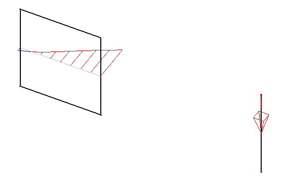
- Precise: raw computed results, without alteration
- Trapezoidal: trapezoidal regression of diagram, for each 2D member separately
- None: the diagram is hidden
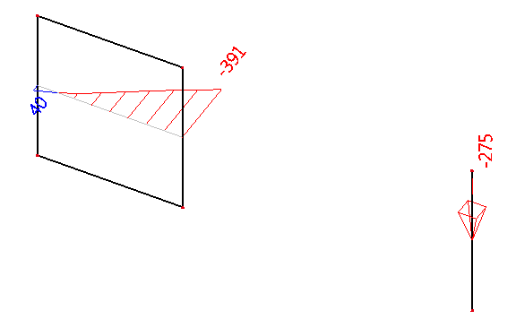
Display total value
when ticked, the integral value of the displayed diagram is written, for each 2D member separately
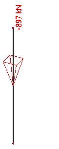
Display average value
when ticked, the average value of the displayed diagram is written and the corresponding uniform diagram is drawn, for each 2D member separately
Result type Resulting forces – Member grouping per member
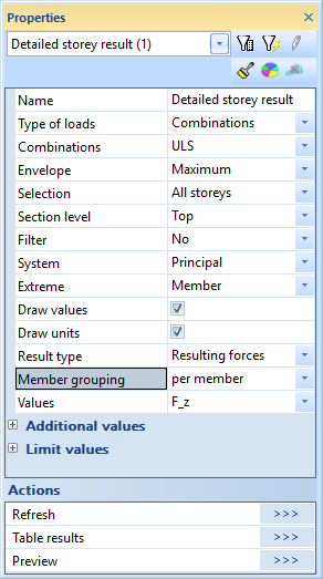
Only settings that behave differently from previous paragraph are listed here. For information about settings that are not listed here, please refer to previous paragraph “Internal forces”.
Result type
selection of result type; possible choices are
- internal forces
- resulting forces
Member grouping
selection of location type for resulting forces; possible choices are
- per member: the resulting forces are computed for each supporting member separately
- per storey: the resulting forces are computed for each storey, considering all the supporting members at once; 1D (columns) and 2D members (walls) are taken into account together
Resulting forces in 1D members (columns) are identical to internal forces in 1D members.
Resulting forces in 2D members (walls) compute the resultant at the center of each wall, according to a dedicated local coordinate system, regardless of the System output setting. The coordinate system that is used is the same as the LCS of a vertical rib placed in the middle of the wall. It is also the same coordinate system that is used for integration strips.
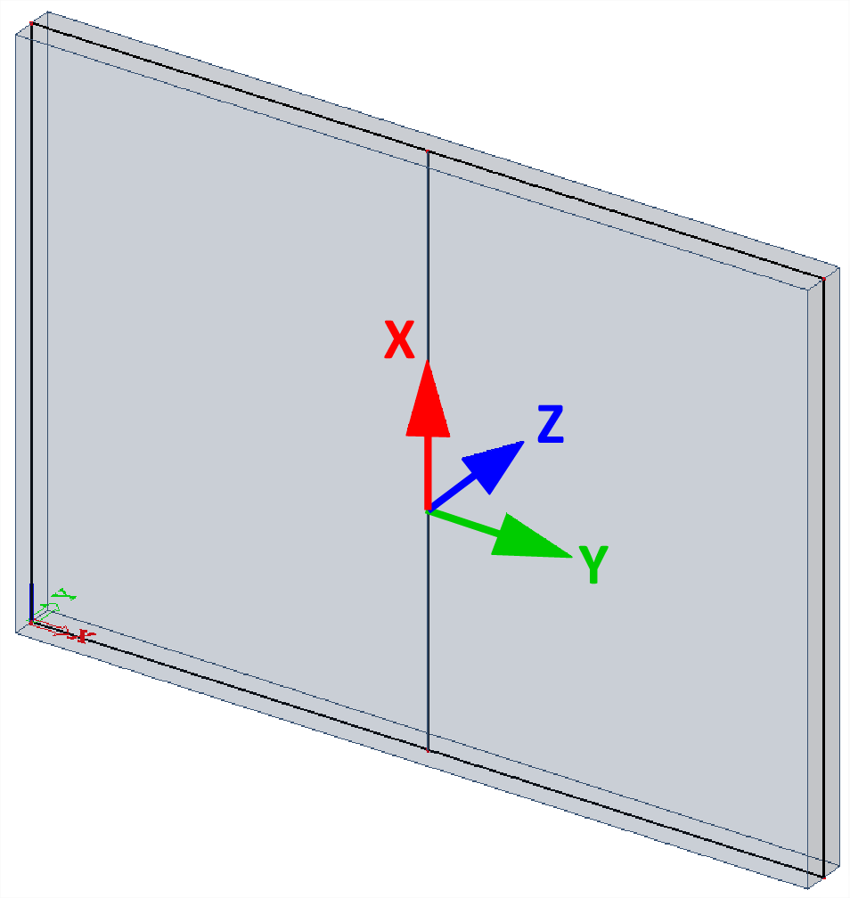
- The local X-axis is vertical, upwards
- The local Z-axis is identical to the Z-LCS of the wall
- Y = Z ^ X
In this way, resulting forces in walls can be easily displayed together, consistently with internal forces in columns on a single drawing.
Result type Resulting forces – Member grouping per storey
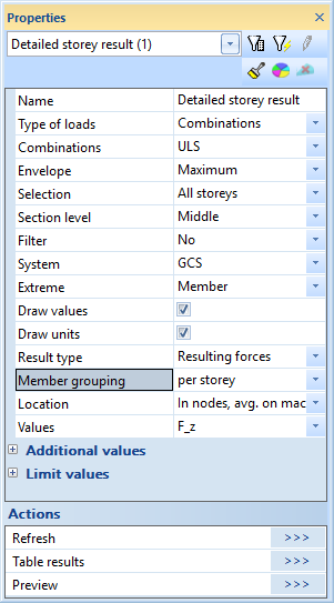
Only settings that behave differently from paragraph “Internal forces” are listed here. For information about settings that are not listed here, please refer to paragraph “Internal forces”.
Result type
selection of result type; possible choices are
- internal forces
- resulting forces
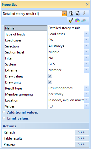
Member grouping
selection of location type for resulting forces; possible choices are
- per member: the resulting forces are computed for each supporting member separately
- per storey: the resulting forces are computed for each storey, considering all the supporting members at once; 1D (columns) and 2D members (walls) are taken into account together
Location
defines how values are obtained from the 2D finite elements, using various interpolation methods (for more information, see Location)
System
selection of coordinate system for output of resulting forces by storey; possible choices are
- GCS
- UCS
UCS
selection of a UCS from the UCS library, to be used as reference system for output of resulting forces by storey
Values
main component of resulting force; possible choices are
Fx, Fy, Fz = resulting force according to X,Y,Z axis of selected coordinate system
Mx,My,Mz = resulting moment around X,Y,Z axis of selected coordinate system
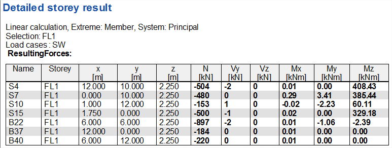
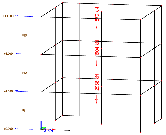
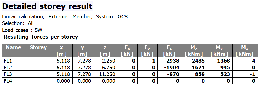
Some examples
Output of total vertical forces in all storeys (load descending)
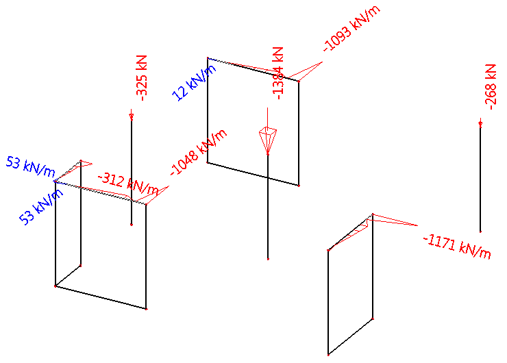
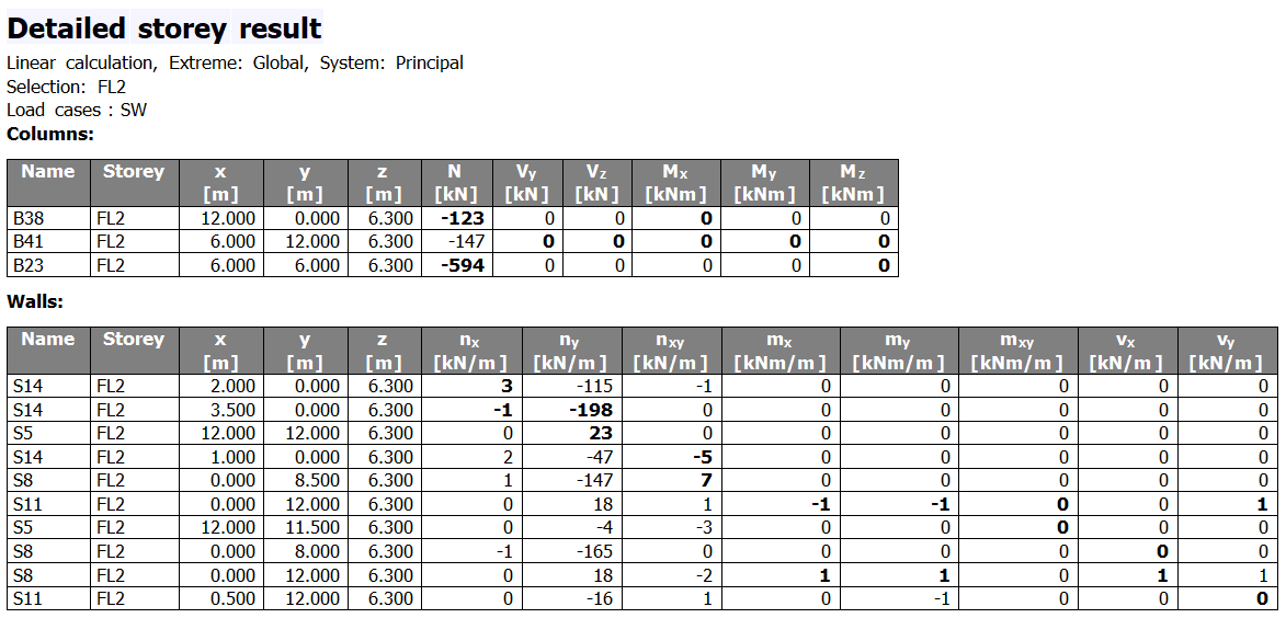
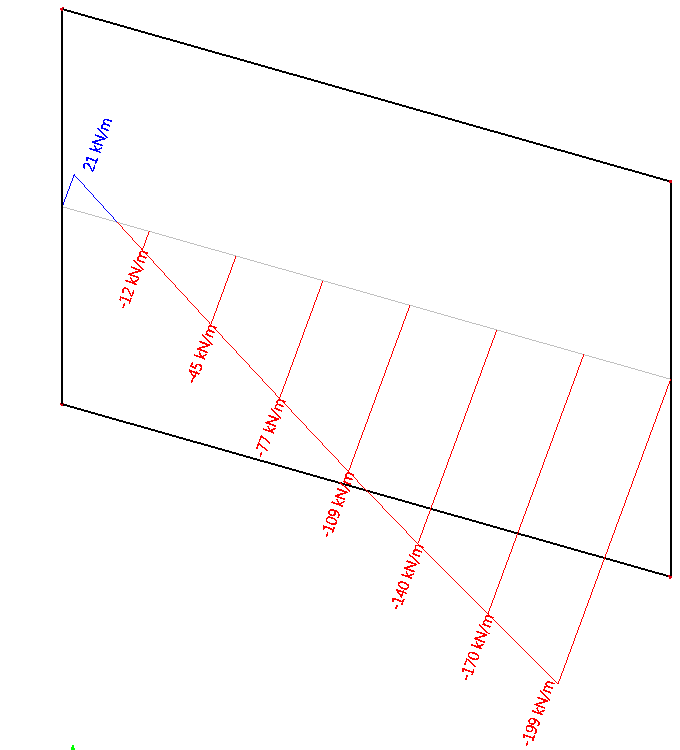
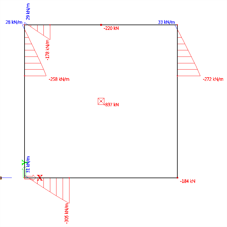
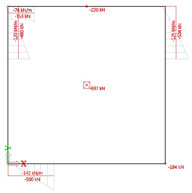
Internal forces in all supporting members of a storey
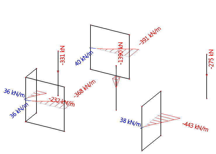
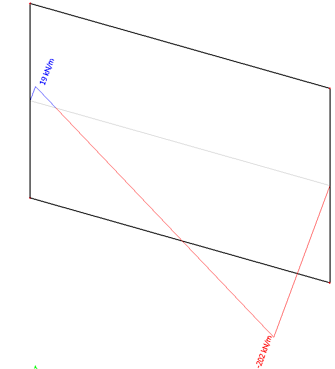
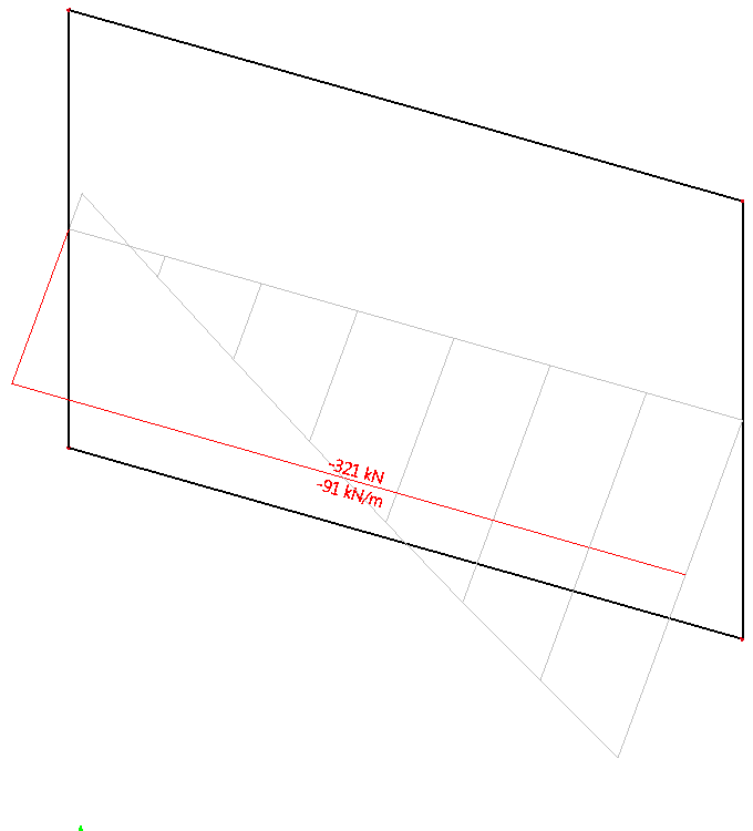
Average forces in all supporting members of a storey
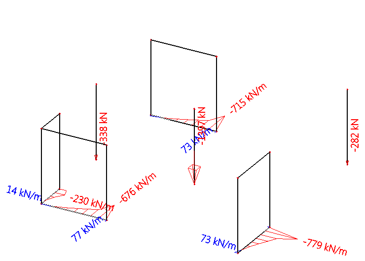
Resulting forces in all supporting members of a storey