Membrane elements
Definition, application
Membrane elements are shell elements with zero flexural stiffness and zero axial compression stiffness. This behaviour is nonlinear and it is necessary to run " Nonlinear calculation" for taken it into account.
Where to find it
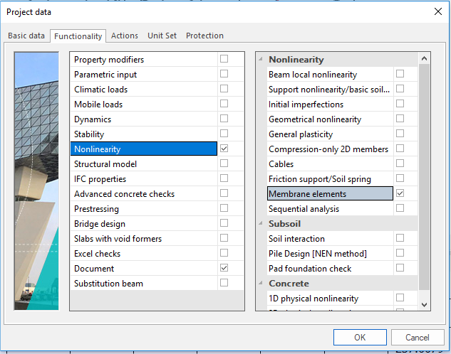
In project data dialog in part 'Functionality' it is necessary to switch ON 'Membrane elements'. After that in properties of 2D members there is new possibility 'Membrane'.
How to create new one
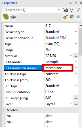
In properties of 2D member it is necessary to switch 'FEM nonlinear model' on 'Membrane'.
Prerequisites
In Project settings > Functionality options Nonlinearity > Membrane elements and "Geometrical nonlinearity" must be selected.
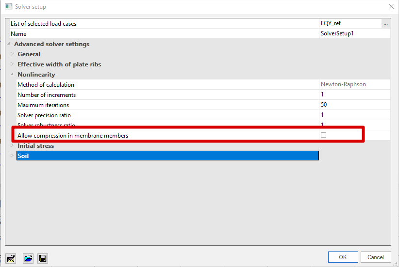
In Calculation, Mesh > Solver Setup the parameter Nonlinearity > Geometrical nonlinearity – 3rd order must be set and " Newton-Raphson method" (even the Modified Newton-Raphson is not allowed for this type of calculation).
In solver setup there is one possibility 'Allow compression in membrane members' which allow take into account membrane member in compression.
Usually the nonlinear calculation must be run in order to obtain realistic results. This means that at least one nonlinear combination must be defined.
Note: Technically speaking, SCIA Engineer allows you to run even a linear calculation with the membrane members defined, but the results may be seriously affected (negatively) by the one-step solution. Therefore, in general, use the nonlinear calculation for the membrane members.
Limitations
-
Membrane elements can be modelled in general XYZ – environment only.
-
It is not possible to calculate CDD for these membrane elements.
-
It is not possible to set orthotropic parameters for the membrane elements.
-
It is not possible to define ribs for these membrane elements.
-
It is not possible to define prestressed tendons for these elements.
-
It is not possible to use other, steel and aluminium materials.
-
It is not possible to set physical non-linearity for these elements.
Results
With regard to the theoretical assumptions some of the internal forces in membrane elements are not defined (are zero):
|
mx |
zero (see the fig. below) |
|
my |
zero |
|
mxy |
zero |
|
qx |
zero |
|
qy |
zero |
|
nx |
defined |
|
ny |
defined |
|
qxy |
defined |
Differences in the results between membrane and standard element
The difference in the obtained results resulting from the application of the membrane behaviour can be best demonstrated on a simple example. Let us assume a rectangular plate made of a very thin sheet of steel. The left-hand side of the figure shows the results obtained for a standard 2D element. The right-hand side then contains the results for the membrane elements.
Moment mx

Stress Sigma X+
