Definition of a composite deck
A deck (composite deck or metal deck) is essentially a plate in SCIA Engineer. It may be input as any 2D member that accepts ribs. That includes plates and straight walls.
To define a composite deck, the user would usually define a standard plate, or a ribbed plate in the case that he would like to assign the ribs in the very same modelling operation.
A composite deck is created from a standard plate via the property Element type. This property defines whether the 2D member is a standard plate, a composite deck, or a metal deck.
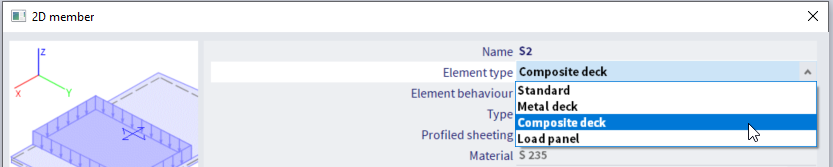
When using the shortcuts Composite deck or Metal deck of the service tree, the appropriate Element type is directly selected.
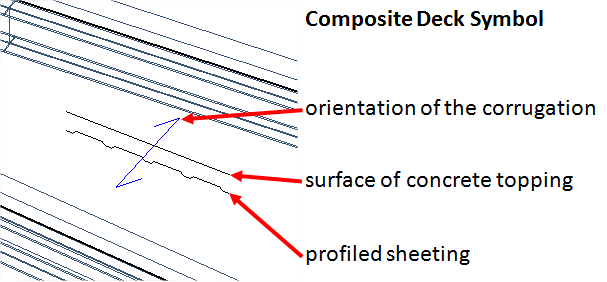
A composite deck is made of a profiled steel sheeting with a concrete topping.
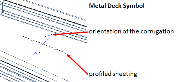
A metal deck has only the profiled steel sheeting (usually intended for light-weight roofs).
A standard plate may be used in a model that contains also one or more composite/metal decks, but it will not have any of the composite analysis features.
The specific properties for a composite/metal deck are:
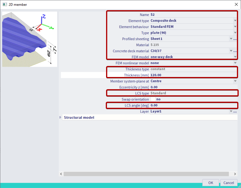
| Element type |
standard: standard plate, with regular properties; metal deck: profiled steel sheeting alone (1 layer) composite deck: 2-layers member, profiled steel sheeting + concrete topping load panel: the 2D member acts as a load panel, i.e. redistributes loads to the underlying beams and walls, but has not stiffness; a member with this setting will not be affected by the CAM |
| Element behaviour |
Standard FEM: the member acts as a standard FEM plate, with bending and in-plane stiffness properties calculated according to the properties of the deck Flexible diaphragm: the member has no in-plane shear stiffness nor bending stiffness; in-plane loading can be transferred only axially, without transverse diffusion. However, its self-weight is taken into account and its geometry and mechanical properties are taken into account for the calculation of the characteristics of the attached composite beams; no results are available for the 2D member itself; this behaviour is selected by default for metal decks Rigid diaphragm: all characteristics of the flexible diaphragm apply, except that a rigid constraint is applied for all in-plane displacements; the diaphragm acts as a rigid body for in-plane displacements, but is entirely flexible for out-of-plane displacements; this behaviour is selected by default for composite decks Semi-rigid diaphragm: all characteristics of the flexible diaphragm apply, except that the real in-plane stiffness of the deck is taken into account in the FEM analysis; the deck has its real in-plane stiffness, but no bending stiffness This setting can be edited only for Element type = composite deck or metal deck. When Element type = Standard, it is read-only and set to Standard FEM. When Element type = Load panel, it is not available. See Theoretical background for more details. |
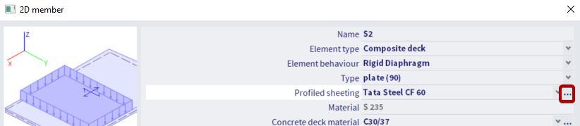
| Profiled Sheeting | selection of a profiled steel sheeting from the library (see below) |
| Material | material of the selected profiled steel sheeting; this property is read-only and its value is taken from the profiled sheeting library |
| Concrete deck material | material of the concrete topping (only for composite deck) |
| FEM model |
one-way deck: the deck transfers loads in a one-way manner; |
| Thickness type | read-only; constant; this cannot be edited for composite/ metal decks |
| Thickness | for metal deck: read-only; height of the selected profiled sheeting for composite: editable; total height of the composite deck; may not be smaller than the height of the selected profiled sheeting |
| LCS Type | read-only; standard; only standard LCS type allowed for composite/metal decks |
| LCS Angle | same meaning as usual, but additionally defines the orientation of the corrugation of the profiled sheeting; the corrugation of the sheeting is always directed along the LCS Y axis |
When a diaphragm behaviour is selected, additional settings are available for load transfer (load panel functionality of the diaphragm). See the chapter related to load panels for more information.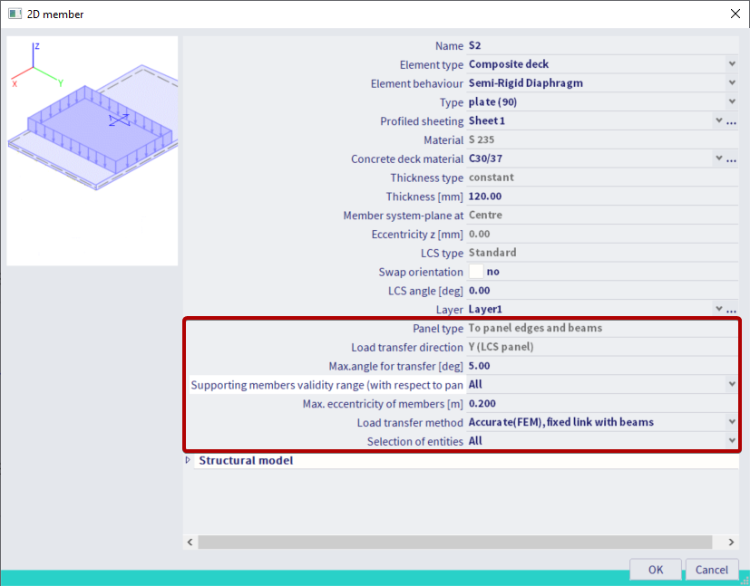
For dynamic analysis, depending on the element type and element behaviour, the masses must be configured in an appropriate way. See the chapter related to using diaphragms in dynamic analysis.
When a composite beam is defined using the composite analysis model, the information about the profiled steel sheeting is automatically taken into account in the LTB check of the steel code check.
Profiled sheeting library
The profiled sheeting library can be accessed from the properties of a composite or metal deck or directly in the Libraries composite sub-tree. It is the same library that is used for diaphragm constraints in steel code checks for LTB stabilization.
The properties of the profiled steel sheeting are divided in 4 groups.
some general properties (name, etc...)
Manufacturer properties, which are used only in the case of diaphragm constraints in the steel code checks; those will not be described here
Geometry, which defines the main dimensions of the profiled sheeting
Orthotropic properties, which define the mechanical properties of the sheeting for the CAM
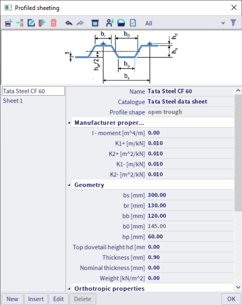
| Name | name of the profiled sheeting library item |
| Catalogue | user defined text field; may be used to define lists of profiled sheeting and filter the available profiled sheetings in the library; it can be, for instance, the manufacturer's name, some type of sheeting, etc... |
| Profile shape |
type of profile shape; it is automatically determined from the geometry of the profile; it can be open trough
or re-entrant trough
|
|
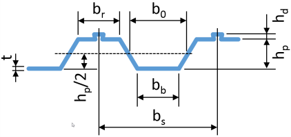
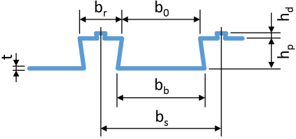
bs, br, bb, b0, hp |
dimensions of the profiled sheeting, as shown in the pictures above; b0 is read-only and calculated from the other dimensions |
| Top dovetail height hd | height of the top dovetail detail, as shown in picture; it is not used in the CAM; it is taken into account in some checks |
| Thickness | thickness of the sheeting |
| Nominal thickness | nominal thickness; not used for the CAM |
| Weight | surface weight of the sheeting; not used for the CAM; the self-weight of the sheeting is calculated from its geometry |
| Material | steel material of the sheeting |
| Automatic calculation |
when ON, the orthotropic properties of the profiled sheeting are calculated from the geometry ("Composite Analysis Model - Theoretical background"); when OFF, the components of the orthotropy matrix may be defined manually |
| D11 ... d33 | components of the orthotropy matrix of the profiled sheeting |
Display settings
For composite and metal decks, it is possible to display the shape and orientation of the profiled sheeting directly on the model. The corresponding view settings are located in the Composite tab of the general view settings:
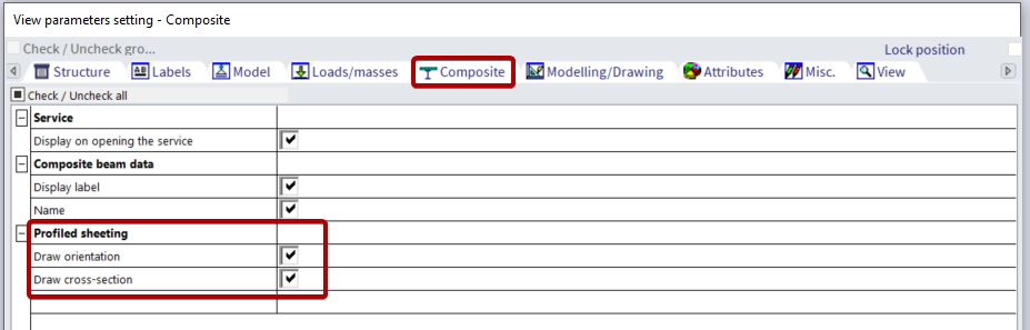
Those settings allow to display on the model symbols that show the main supporting direction (i.e. the direction of the profiled sheeting), the shape of the profiled sheeting and the thickness of the concrete topping.