7 Design of non-prestressed reinforcement
7.1 Concrete 2D data
The user can overwrite the default global settings with local settings defined for selected members by creating member data. Simply said, in members where the user does not want to use the global concrete settings, he creates local concrete settings by defining the member data. We recognize two types of these local settings for 2D concrete members
- Member data
- Punching data (more in chapter "8.1 Punching data")
These member data may be created by selecting these two items in Concrete Advanced tree and choosing the proper 2D member, where this data should be defined. These newly created settings will be loaded from default global settings and can be changed to fit the user needs.
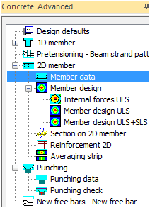
Fig. 39 Concrete tress with concrete member data
Concrete member data for slab S138 can look as following
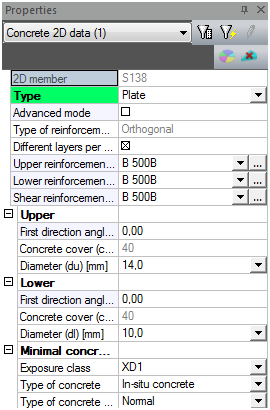
Fig. 40 Concrete member data for slab S138
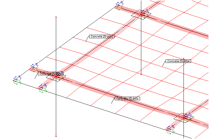
Fig. 41 Concrete member data in 3D window
7.2 User reinforcement
Effects of prestressing for design of non-prestressed reinforcement in 2D members in version SCIA Engineer 2011 are taken into account automatically only partially.
Internal forces are taken automatically into design but area of prestressing reinforcement is not taken automatically. This causes another workaround how to take amount of prestressing reinforcement into account for design or other checks.
The real post-tensioned tendon can be substituted by the nonprestressed reinforcement which is inputted as Freebars. The Freebars can be input from Concrete Advanced > Freebars. The geometry of the freebars will be the same as the geometry of the postensioned tendon.
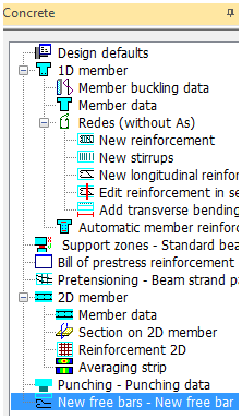
Fig. 42 Freebars in Concrete tree
Material of these freebars has to be also modified. We create completely new material based on the nonprestressed material with modified E modulus to 195 GPa and tendon stresses.
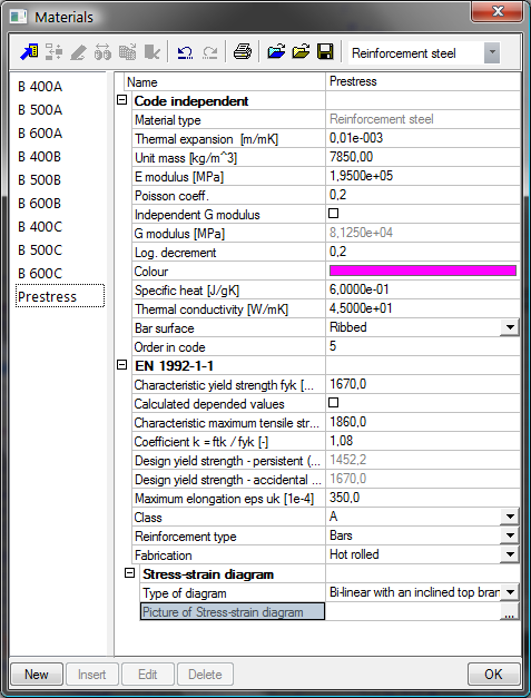
Fig. 43 Fictive prestressing material
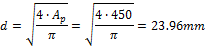
The diameter of the fictive bar is calculated from the area of the strands. We suppose 3 strands in one tendon.

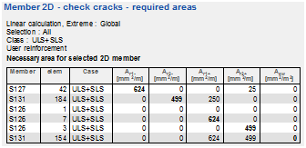
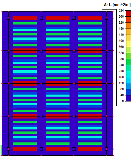
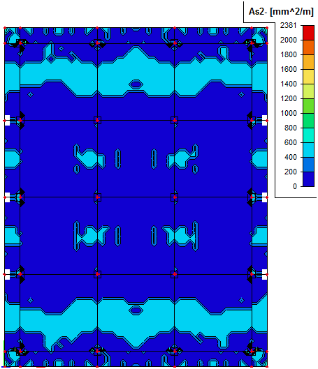
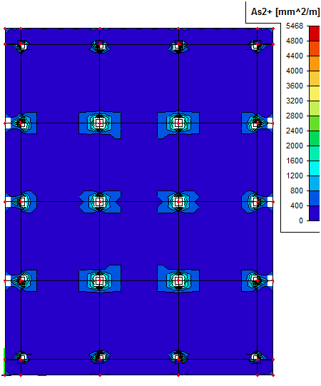
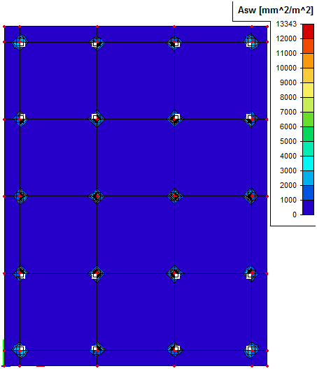
We can display the amount of user defined reinforcement (freebars representing the tendons) in services Design ULS or Design ULS+SLS. In the following table you can see the results for user reinforcement.
This amount can be displayed only if we have the same material of user defined reinforcement and of designed reinforcement. That is why it is necessary to switch material of freebars to B500B.
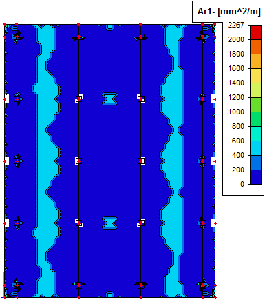
The different colours of strips in the span line are the consequence.
Value Asw is of course equal to zero because no shear user reinforcement is defined in this moment.
|
Lower (-) |
Upper (+) |
|
|---|---|---|
|
As1 |
|
|
|
As2 |
|
|
7.3 Design of necessary area of non-prestressed reinforcement
7.3.1 Design ULS
Design of required area of nonprestressed reinforcement is done in Concrete Advanced > 2D member > Member design > Member design ULS.
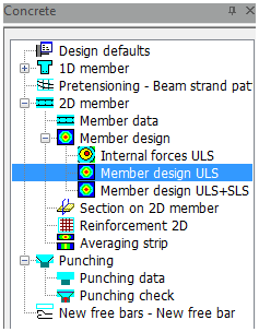
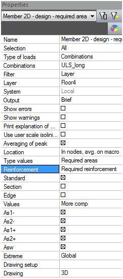
Fig. 44 Design ULS in the tree
Before design procedure starts we recommend that the user checks the settings for detailing provisions of 2D structures in Concrete setup > detailing provisions >2D structures and slabs.
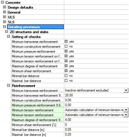
Fig. 45 Detailing provisions for 2D in concrete setup
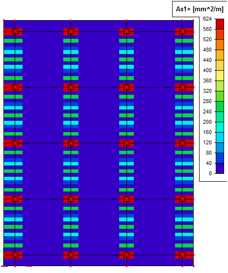
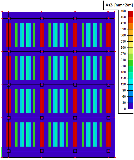
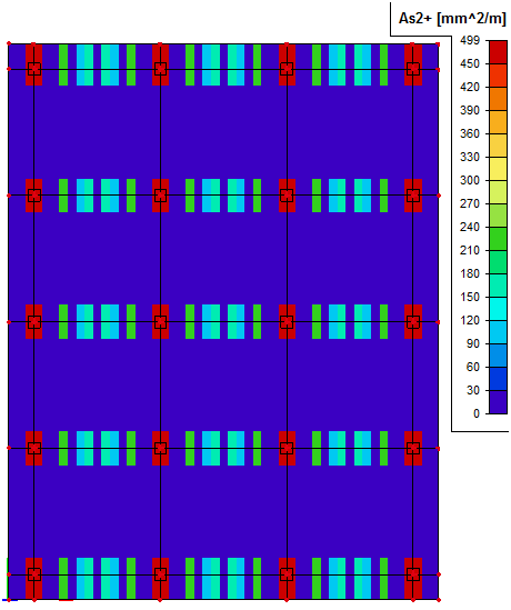
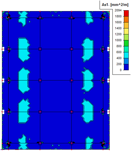
We can split design reinforcement into five groups:
|
As1- |
required area of lower reinforcement in the direction 1 |
|
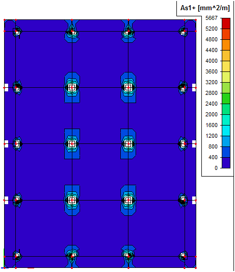
As1+ |
required area of upper reinforcement in the direction 1 |
|
As2- |
required area of lower reinforcement in the direction 2 |
|
As2+ |
required area of upper reinforcement in the direction 2 |
|
Asw |
required area of shear reinforcement |
In our example there is certain amount of postensioned tendons. So we could design only Additional reinforcement which is needed to be added to the current reinforcement, but due to the problem mentioned in the note in chapter "7.1 Concrete 2D data " (different materials) we have to calculated Required reinforcement and decrease this amount by the user reinforcement. This is the procedure how we can get the additional amount of reinforcement. The results mentioned below are evaluated for the real tendon structure for combination ULS_long and they cover the shear effect in SR2.
|
Type of output |
Lower (-) |
Upper (+) |
|---|---|---|
|
As1 |
|
|
|
As2 |
|
|
|
Asw |
|
|
7.3.2 Design ULS+SLS
Design of necessary area of nonprestressed reinforcement is done in Concrete Advanced > 2D member > Member design > Member design ULS+SLS. The theory of the design is explained in details in [5].
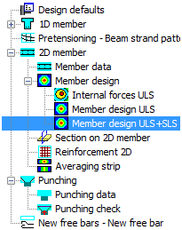
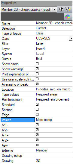
Fig. 46 Design ULS+SLS
The procedure of the design of the nonprestressed reinforcement for both states (ULS+SLS) is done in the following steps.
- Design of required reinforcement for ULS
- Design of required reinforcement for SLS
- Design for SLS means the minimal area of reinforcement for reaching maximal allowable value of crack width (depending on the exposure class).
- Check of reinforcement designed for ULS is satisfied for SLS too
- IF Yes THEN Design is finished
- IF No THEN Design of additional reinforcement between SLS and ULS
Design SLS does not calculate reinforcement with respect to Stress limitation or Deformation.
Limited values of crack width are not implemented in Release 2010.1. It means the user have to adapt manually maximal crack width for nonprestressed concrete in concrete setup. But in our case we use monostrands which are unbonded tendons and the limited values are the same as for nonprestressed concrete.
The classes are required for Design ULS+SLS. The classes are described in chapter "2.6 Classes". Only one class which contains ULS_long and SLS_QP_long is needed.
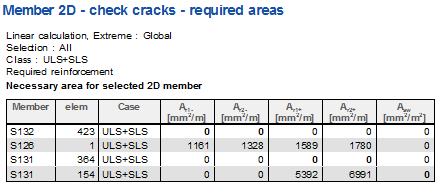
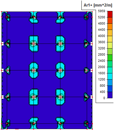
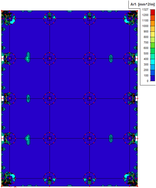
The required additional areas for class ULS+SLS for each surface and direction are the following. We can split design reinforcement into five groups:
|
Ar1- |
required area of lower reinforcement in the direction 1 |
|
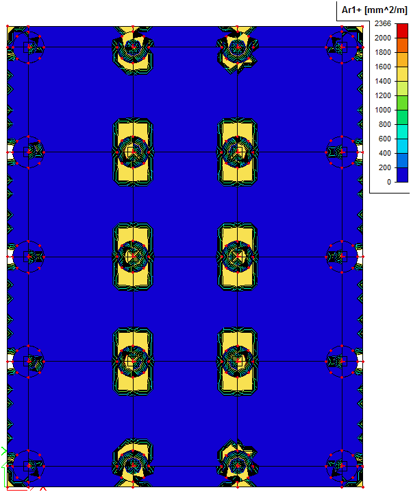
Ar1+ |
required area of upper reinforcement in the direction 1 |
|
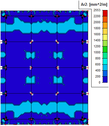
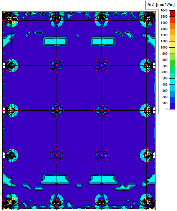
Ar2- |
required area of lower reinforcement in the direction 2 |
|
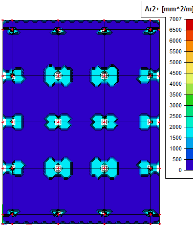
Ar2+ |
required area of upper reinforcement in the direction 2 |
|
Asw |
required area of shear reinforcement |
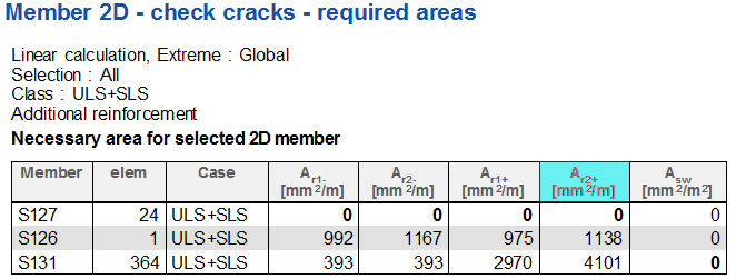
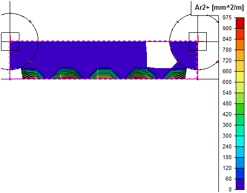
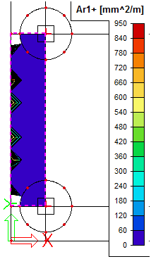
7.3.2.1 Design of longitudinal reinforcement with shear effect considered in SR2
The results mentioned below are evaluated for real tendon structure for combination class ULS+SLS (ULS_long+SLS_QP_long) and they cover the shear effect in SR2.
|
Output |
Lower (-) |
Upper (+) |
|---|---|---|
|
Ar1 |
|
|
|
Ar2 |
|
|
The 2D structure is prestressed. Warning W18 appears for this type of structure and other warnings or errors are in the background. It is suitable to set OFF W18 in concrete solver and then you can see the particular warnings and errors in the structure. But this is not possible in the current version.
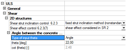
7.3.2.2 Design of shear reinforcement
The evaluation of the required areas of shear reinforcement can be done for
- Variable strut inclination – program optimizes the angle theta (recommended)
- Fixed strut inclination - value of cotangent is set to 2.48 (max =2.5)
The results of the required areas are displayed in the following table for real tendon and slab S138 again. You can see the required areas are lower for the case with the fixed strut inclination.
|
Asw |
|
|
Fixed strut inclination |
Variable strut inclination |
|
|
|
|
|
|
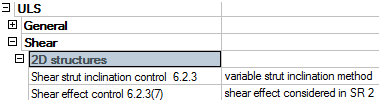
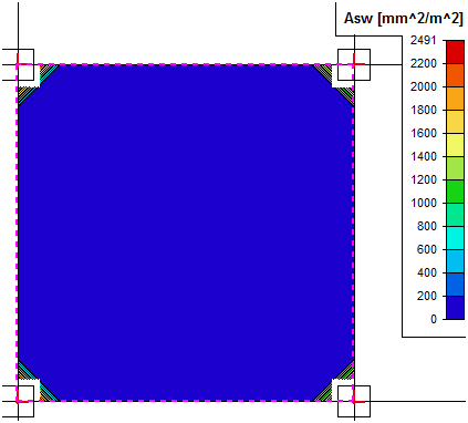
The recommended option is use variable strut inclination.
7.3.3 Summary from Design ULS+SLS of longitudinal reinforcement
The biggest required areas are for the upper reinforcement above columns. These regions are problematic during our design for several reasons
- Shear effect - the regions above columns are very sensitive to taking or not taking into account the shear effect on required areas of longitudinal reinforcement. If we can neglect shear effect we get much lower values of the required areas. The explanation when we can neglect shear effect are the following:
- Punching check - the shear effect can be verified by this design or can be checked also during punching check (Maximal concrete strut capacity). That is why we can neglect shear effect for design of longitudinal reinforcement if we also perform punching check.
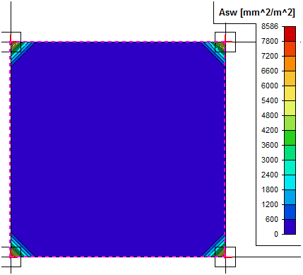
- Limits for additional force caused by shear – chapter 6.2.3(7) describes the limit for the additional longitudinal force due to shear (Med,max/z). This limit is not verified by the program. That is why much higher longitudinal forces (higher than allowed) can be taken into account during design. Again we can compare the values for slab S138 with the real tendon
|
Slab S138 |
mx [kNm/m] |
my [kNm/m] |
|---|---|---|
|
m |
|
|
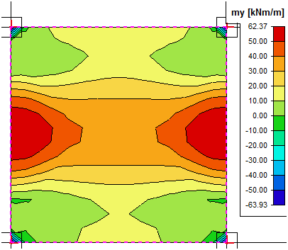
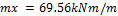
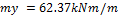

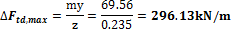
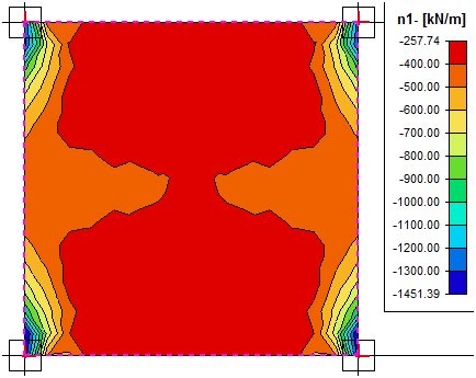
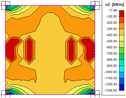
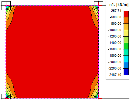
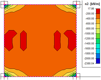
If you look in the table below you can see the values of additional longitudinal forces due to shear. You get these values when you calculate the difference between values with (SR2) and without shear effect. The values near the support are almost twice bigger in the case that you consider the shear effect. Then the additional longitudinal force due to shear is the following

This value is much higher (3x) than allowed. From the investigation above we can assume that we can neglect the shear effect because we get very high value of additional longitudinal force due to shear.
|
Slab S138 |
n1- [kN/m] |
n2- [kN/m] |
|---|---|---|
|
No shear effect |
|
|
|
Shear effect in SR2 |
|
|
- Maximal percentage of the reinforcement – another limit during the design seems to be the maximal percentage of reinforcement. The default value is 4% (9.2.1.1(3) from "EN 1992-1-1 Eurocode 2, Design of Concrete Structures – Part 1: General rules and rules for buildings, European Committee for Standardization, December 2004."). This limit is exceeded for this case (see non-designable places above columns for the case with the real tendon). If we increase this percentage to 5% the reinforcement can be designed with respect to this condition.
German national annex allows for reinforcement up to 8% of concrete areas. It means that increasing the percentage from 4% to 5% will probably not affect the structural design and could be done. But we do not meet the strict general Eurocode.
You can find the results for the structure with the real tendon and for the slab S138, class ULS+SLS for the upper reinforcement (Ar1+) in the following table.
|
Slab S138 |
4% |
5% |
|---|---|---|
|
No shear effect |
|
|
|
SR2 |
|
|
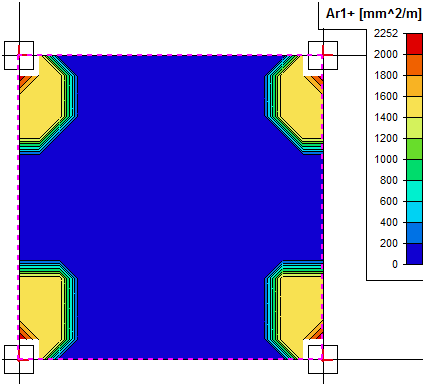
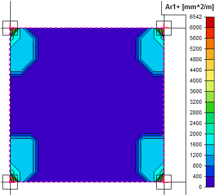
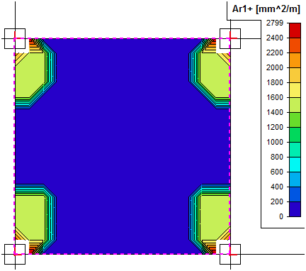
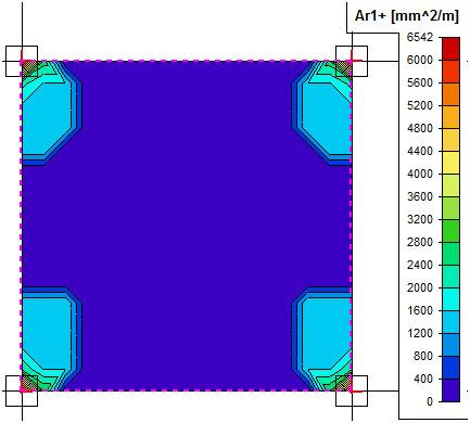
However if we neglect shear effect we still get some non-designable places above columns (empty areas above columns for no shear effect and 4% reinforcement limit). The solution is to introduce columns with head (see chapter "7.4 Definition of column head".)
7.4 Definition of column head
Due to reason described in the previous chapters it seems to be efficient to introduce column heads in the structure. The column heads as in the following figure have been modelled. Based on the span L = 9.0 m the outermost distance is 2.7 m and the inner effective distance is 1.8 m (see following figure). Depth of the head is 0.625 + 0.290 = 0.915 m.
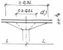
Fig. 47 Dimensions of column head
The column head are modelled as subregions in the existing slabs. The subregions are defined from the Structure > 2D member > 2D members components.
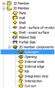
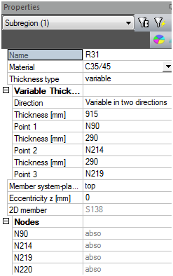
Fig. 48 Subregions
The 3D screen of the structure with column heads is in the following figure.
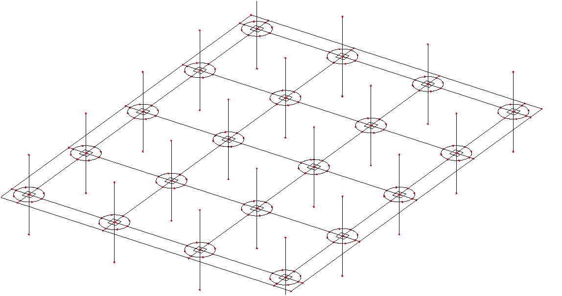
Fig. 49 General overview of the slab with column heads
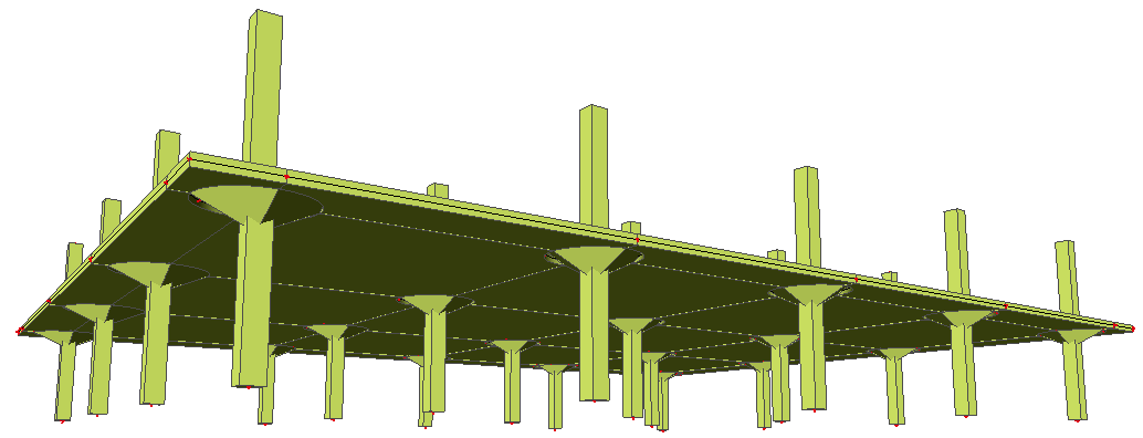
Fig. 50 Rendered 3D model of slab with column head
The local mesh refinement should be introduced above the column heads. Generally, the mesh size with the length of the finite element equal to 0.6 m is used. Linear local mesh refinement with ratio 1.5 should be used above the column heads. Local mesh refinement is defined from the Calculation, mesh > Local mesh refinement > Node mesh refinement. This option depends on the level of the project (Advanced level is required).
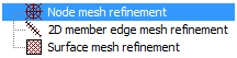
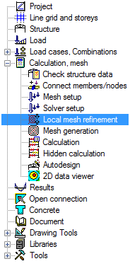
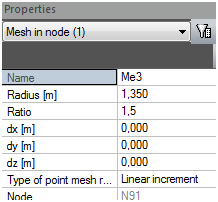
Fig. 51 Local mesh refinement
The local mesh refinement is graphically displayed using balls.
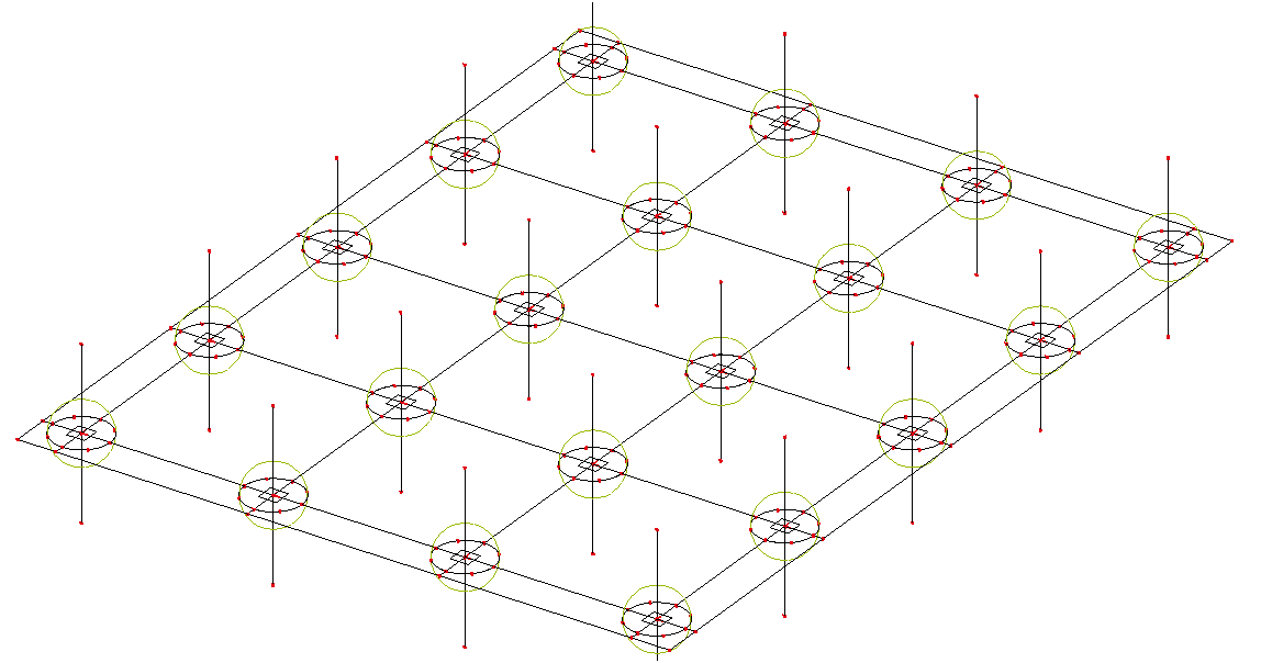
Fig. 52 Local mesh refinement on the whole structure
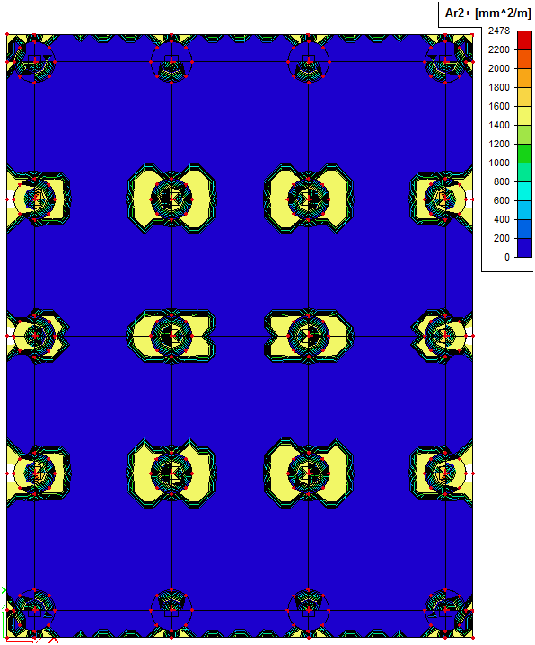
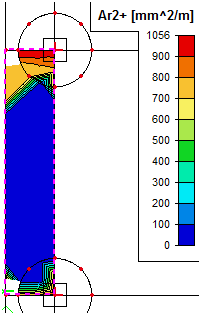
7.4.1.1 Design of longitudinal reinforcement for structure with column heads
During preparation of this tutorial was found that the best evaluation of the required areas for this type of structure is location In nodes avg.
The results mentioned below are evaluated for the real tendon structure with column heads for combination class ULS+SLS (ULS_long+SLS_QP_long) and these results are without shear effect (see chapter "7.3.3 Summary from Design ULS+SLS of longitudinal reinforcement")
|
Output |
Lower (-) |
Upper (+) |
|---|---|---|
|
Ar1 |
|
|
|
Ar2 |
|
|
When we focus again on the slab S138 then we can see the exact values of the required areas. For the external column we can investigate also slab S128 and S135.
|
Output |
Ar1+ |
Ar2+ |
|---|---|---|
|
S138 |
|
|
|
S128 |
|
|
|
S135 |
|
|
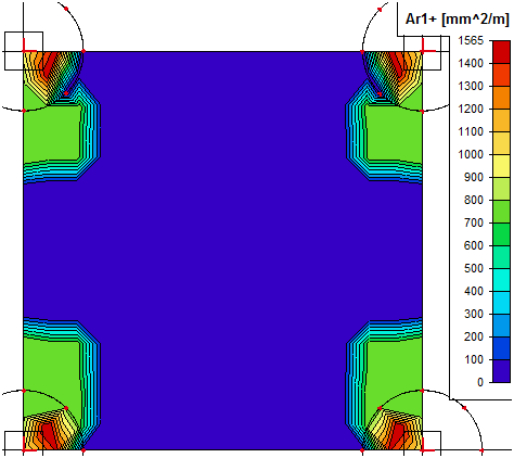
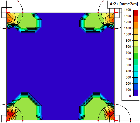
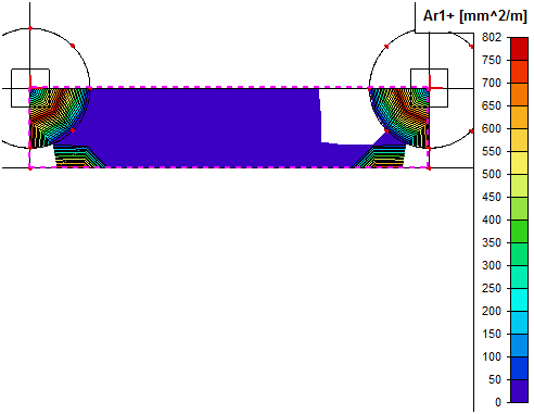
These areas are total required areas. There is also user reinforcement by the tendons. So the amount of additional reinforcement is the difference between the user and required areas. You can see the detail of required areas for each region in the following table.
|
[mm2/m] |
Span |
Column internal |
Column external |
|||
|---|---|---|---|---|---|---|
|
Lower 1 |
Lower2 |
Upper 1 |
Upper 2 |
Upper 1 |
Upper 2 |
|
|
Total required reinf |
400 |
500 |
1565 |
1409 |
802 |
1056 |
|
User reinf |
240 |
240 |
624 |
624 |
624 |
624 |
|
Additional reinf |
160 |
260 |
941 |
785 |
178 |
432 |
|
Reinf |
8 a 150mm |
8 a 150mm |
14 a 150mm |
14a 150mm |
14 a 300mm |
14 a 300mm |
There are also some special regions in the slab where the prestressing tendons are anchored. The intensity of the stresses is too high in this regions and that is why it is not possible to design such regions. Special analysis, for example strut and tie analysis, should be done for proper investigation of the zone below anchors. This is not part of this manual.
7.5 Definition of additional required reinforcement
Additional nonprestressed reinforcement was designed for each surface in ULS+SLS in the chapter above. Now these required areas should be defined as the user real reinforcement. The reinforcement above columns should be designed in the rectangular areas at least L/4 in each direction above the columns. We increase the value to L/3.5 for the internal columns. It means rectangular mesh reinforcement.
- 5.1 m x 5.1 m above the internal columns
- 3.6 m x 3.6 m above the external columns
7.5.1 Definition of additional longitudinal reinforcement
The additional longitudinal reinforcement is defined via service Concrete Advanced > 2D member > Reinforcement 2D.
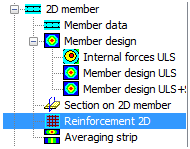
Fig. 53 Reinforcement 2D
Finally the additional reinforcement will be added as calculated in the previous chapter. We can add bars or mesh reinforcement. The settings of the reinforcement for both surfaces are the following:
|
Lower (-) |
Upper (+) |
|---|---|
|
|
|
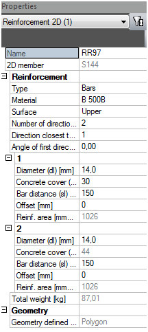
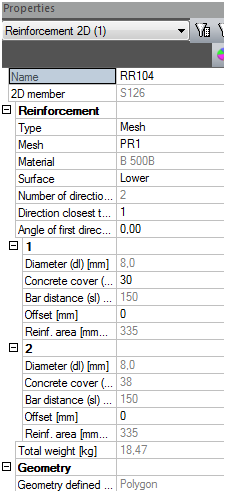
The current version of SCIA Engineer is not able to calculate additional reinforcement with more material of nonprestressed reinforcement
The reinforcement can be displayed for each surface separately. Final shape of lower and upper 2D user reinforcement is the following.
|
Lower (-) |
Upper (+) |
|---|---|
|
|
|
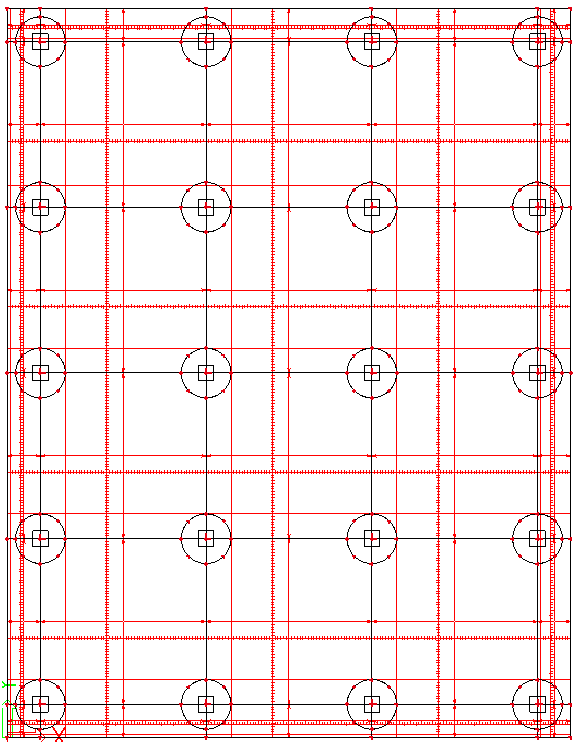
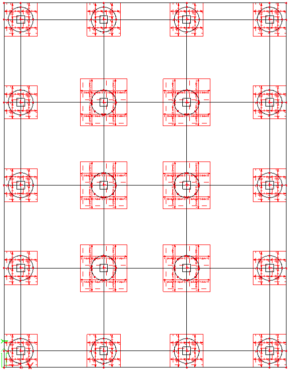
Final reinforcement together with the tendons is the following
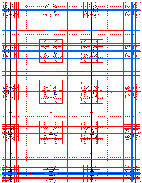
Fig. 54 Final reinforcement in the slab
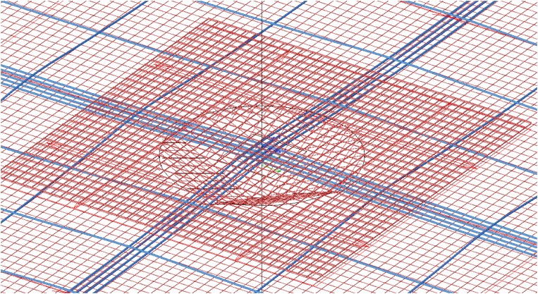
Fig. 55 Detail of the internal column