2 Input
2.1 Material characteristics
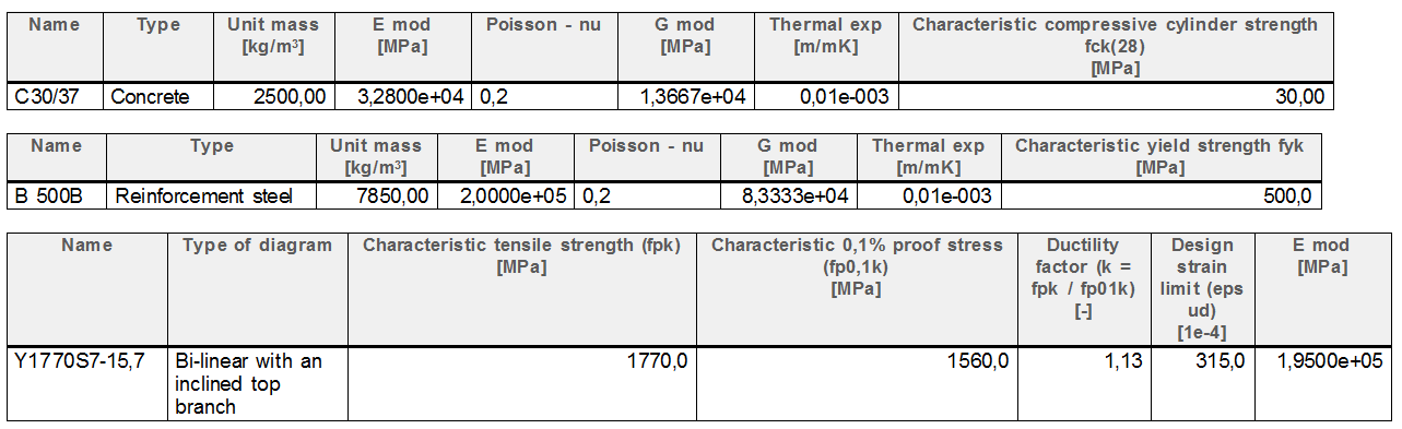
The following material properties have been considered:
− Concrete grade C35/45
|
Characteristic compressive strength |
fck = 35.0 MPa; |
|
Design compressive strength: |
fcd = 23.3 MPa; |
|
Mean value of tensile strength: |
fctm = 3.20 MPa; |
|
Modulus of elasticity: |
Ec = 34.1 GPa; |
|
Shear modulus: |
G = 14.2 GPa |
|
Poisson ratio: |
ν = 0.2 |
− Prestressing steel Y1860S7-15,7
|
Characteristic tensile strength |
fpk = 1860 MPa; |
|
0.1% proof stress |
fp0.1k = 1670 MPa |
|
εuk > 35‰ |
|
|
Modulus of elasticity: |
Ep = 195 GPa; |
|
Friction coefficient |
μ = 0.06 |
|
Unintentional angular displacement |
K = 0.0005/m |
|
Relaxation class |
3 (ρ1000 = 4%) |
|
Nominal area |
Ap1 = 150mm2 |
− Reinforcing steel, B 500 B:
|
Characteristic yield strength |
fyk = 500.0 MPa; |
|
Design strength: |
fyd = 434.8 MPa; |
|
Modulus of elasticity: |
Es = 200 GPa. |
2.2 Supports
The whole structure is supported by the fixed rigid point support in the bottom part of the building.
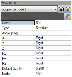
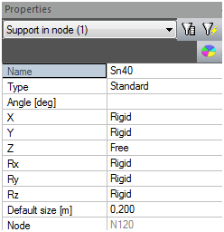
The model of the 4th floor is supported on both ends of the columns. The lower side is fully rigid and the upper side is rigid except in the Z direction where it is free.
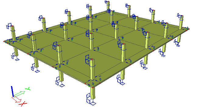
Fig. 4 Model of the 4th floor
|
Lower support |
Upper support |
|
|
Properties |
|
|
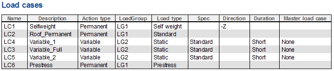
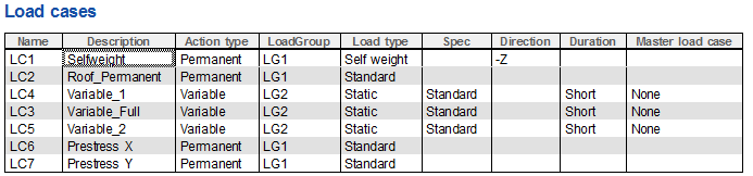
2.3 Loadcases
The following loadcases have been defined in the example. The permanent loadcases LC1; LC2 and LC8 can be assigned to the same load group (LG1). Variable loadcases are stored in LG2 which has an exclusive relation and is in category F. Two permanent loadcases Prestress X and Prestress Y are needed for the model using equivalent load (explained in detail in "4.1.1 Definition of the equivalent load")
2.4 Loads
The load is defined in a standard way. The variable load is used as Variable full. It means all 2D members are subject to the variable load. Load from LC4 – Variable_1 means that only certain parts of the building floor are loaded. An inverse loading scheme as in LC4 is used for loadcase LC5.
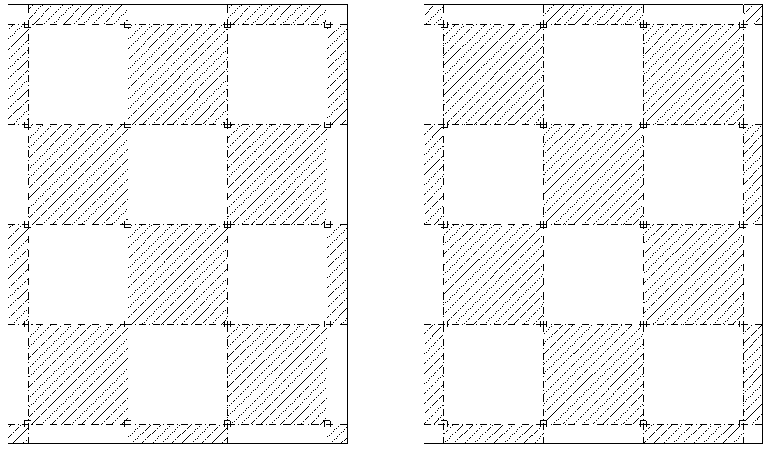
Fig. 5 Extreme position of the variable load
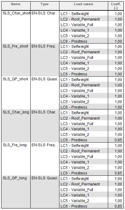
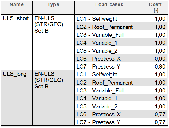
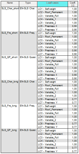
2.5 Combinations
Several combinations are defined in this example. One group is for the ultimate limit state (ULS_short, ULS_long) and the second group is for the serviceability limit state (characteristic, frequent, quasi-permanent). On the following figure you can see only the content of the combination. The load factors are automatically taken into account for each combination in the background. Combinations are defined with respect to the type of modelling of prestressing (real tendon, equivalent load). For more information about both types see chapter "4 Prestressing of 2D members in SCIA Engineer".
2.5.1 Combination in the case of real tendon
When the prestressing is modelled as real tendon then short term losses are calculated automatically. It means that only the reduction for long term losses (estimation 15%) is applied for this case.
2.5.2 Combination in case of equivalent load
When the prestressing is modelled using equivalent load then short term and also long term losses should be estimated. It means reductions for short term (10%) and long term losses (estimation 15%) are applied for this case. Loadcases where prestressing is defined using equivalent load are separated for each direction (Prestress X, Prestress Y).
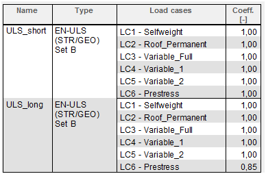
2.6 Classes
The classes are needed for the calculation of required areas during design according to ULS+SLS. Class ULS+SLS was prepared with the following content. The design for both limit states is done for long term losses of prestressing. Combinations ULS_long and SLS_QP_long are selected for the class only.
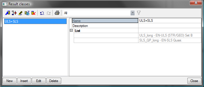
Fig. 6 ULS+SLS class