4 Prestressing of 2D members in SCIA Engineer
The definition of prestressing in 2D members can be done in SCIA Engineer in three ways:
- Definition of the equivalent load – equivalent load is calculated from the geometry and stress in the tendon
- Real tendon in a 1D rib – the tendon is defined in a fictive 1D rib which is part of the 2D slab
- Real tendon in the 2D member directly – the tendon is defined directly in the 2D member using a “hanging node”
Before each option is explained, a short summary of each method is provided.
|
Item |
Equivalent load |
Real tendon in 1D rib |
Real tendon in 2D |
|---|---|---|---|
|
Preparation and definition of the prestressing |
Difficult |
Standard |
Simple |
|
Short term losses |
NO |
YES |
YES |
|
Long term losses |
NO |
NO |
NO |
|
Internal forces from prestressing in design |
YES |
YES |
YES |
|
Area of prestressing in design |
NO (free bars are used) |
NO (free bars duplicate geometry of the tendons) |
NO (free bars duplicate geometry of the tendons) |
|
Design ULS (ULS+SLS) |
YES |
YES |
YES |
|
Check of allowable concrete stresses |
NO |
NO |
NO |
|
Check prestressed capacity or response |
NO |
NO |
NO |
|
Check of prestressing reinforcement |
NO |
YES |
YES (partly) |
|
Check punching shear with respect to prestressing |
YES |
YES |
YES |
|
Code dependent deflection (CDD) |
YES |
NO |
NO |
4.1 Three possibilities of prestressing input
4.1.1 Definition of the equivalent load
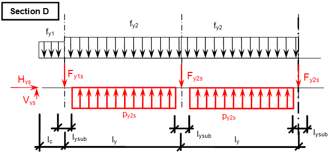
Prestressing can be defined using equivalent load which represents the prestressing tendon. The calculation of the load is dependent on the geometry of the tendon and initial stress in the tendon.
This solution requires time for calculation of all values from the tendon geometry. Parabolic arcs are replaced by the permanent line load (p). Arcs above the supports are replaced by the vertical force representing the arc. Normal force and bending moment are added at the beginning of the tendon.
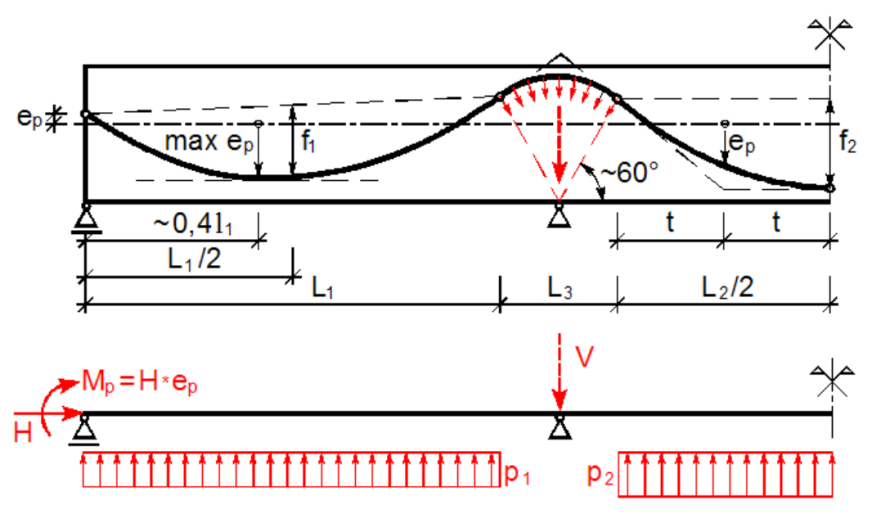
Load balancing method – equivalent load (picture taken from "Navrátil, J., Prestressed concrete structures, Akademické nakladatelství CERM, 2006 (In Czech)")
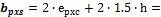
4.1.1.1 Surface equivalent load
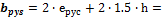
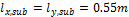
The distribution of the load from prestressing is supposed in the angle of 45 degrees from the centreline of the slab and to the width equal to 1.5*depth of the slab.
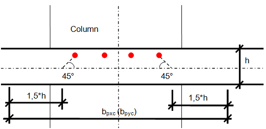
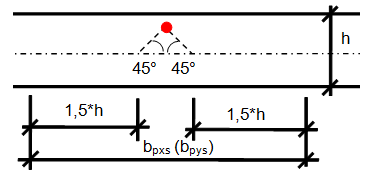
Determination of the spreading width of the prestressing
The spreading width of the prestressing is calculated for the span and for the column line separately.
|
Direction X |
Direction Y |
|
|
Column line |
|
|
|
Span line |
|
|


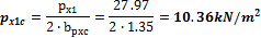
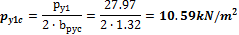
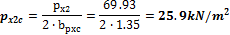
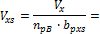
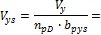
Based on the new spread width the equivalent line load will be recalculated to the equivalent surface load.
|
Direction X |
Direction Y |
||
|
Column line |
1 |
|
|
|
2 |
|
|
|
|
Span line |
1 |
|
|
|
2 |
|
|
|


4.1.1.2 Vertical and horizontal forces in the edges
The horizontal and vertical forces should be presented in the free edges where the tendons are stressed and anchored.
|
Direction X |
Direction Y |
|
|
α [ ° ] |
|
|
|
P [kN] |
2936.25 |
2349.00 |
|
H [kN] |
|
|
|
V [kN] |
|
|


Furthermore those forces are recalculated to the spreading width of prestressing
|
Direction X |
Direction Y |
|||
|
Column line |
Span line |
Column line |
Span line |
|
|
H [kN/m] |
|
|
|
|
|
V [kN/m] |
|
|
|
|


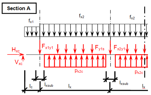
4.1.1.3 Point forces from tendons in column line
When we look in "Fig. 8 Actions of the tendon on the slab (picture taken from http://www.vsl.net/Portals/0/vsl_techreports/PT_Slabs.pdf)" we can see the action of the tendon through the point forces in the column line. These point forces are calculated for each direction and for the column and span line separately. We substitute equivalent load above the support by the point force load. The length of the arc of the tendon above the support is calculated from the inflexion points. We can suppose inflexion points in the edges of the column dimensions. It means for substituted support forces.
Then support point forces are the following
Direction X
- Column line


- Span line – point force for each tendon (


Direction Y
- Column line


- Span line – point force for each tendon (


Two possibilities are available for user to input the prestressing using equivalent load applied on the structure.
- Input in 1 load case - summarize force above the column in both directions (see "Point force above column lines").


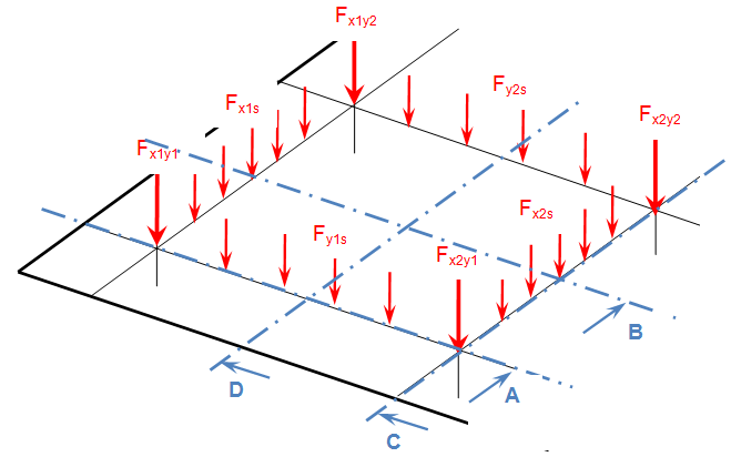
Point force above column lines
- Input in 2 load cases – prestressing defined by the equivalent load is inputted in 2 load cases (prestressing X and prestressing Y). The user has better overview of the prestressing in each direction. In this case the summarization of the point forces above the column cross-link is not applied.
Finally the equivalent load in our case is the following.
Direction X
Direction Y
Disadvantage of this solution is that the short term losses are not calculated automatically and have to be estimated by the user. Furthermore the load is modified with respect to the stress after short term and long term losses.
Typical cases of the prestressing inputted using equivalent load in both directions separately are the following.
|
Prestress X |
Prestress Y |
|
|
|

4.1.2 Real tendon on the 1D rib
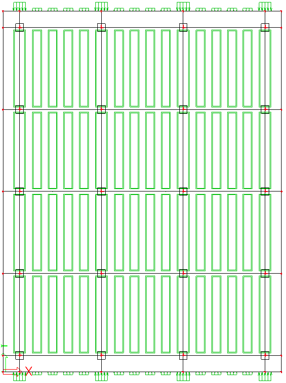
Definition of the prestressing in the postensioned 2D member is done using standard tool Post-tensioned internal tendon. A fictive 1D member has to be defined in the position of the tendons. It means one rib in the column line and one rib for each tendon in the span. The definition is time consuming because you have to define slabs + ribs + tendons. The final screen of that structure is following
Post-tensioned slab with internal ribs
The properties of the ribs are visible in "Properties of the internal rib". The material of the rib is fictive and unity mass is equal to 0.1 kg/m3. Otherwise the self weight of the rib is duplicated to the self weight of the slab.
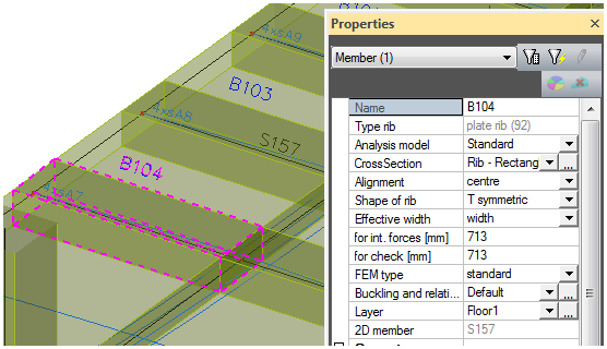
Properties of the internal rib
Allocation of the tendons in this case is for 1D member only.
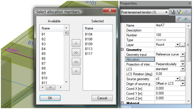
Allocation of the tendon
The check box hanging nodes in Mesh setup can be switched OFF in this case.
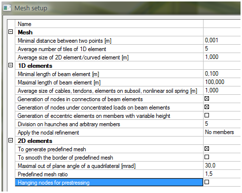
Mesh setup
This option will not be commented and used in the following text.
4.1.3 Real tendon on the 2D member directly
Definition of the prestressing in the post-tensioned 2D member is done again using standard tool Post-tensioned internal tendon. Till version 2007.1 post-tensioning in a 2D member had to be defined on a fictive rib which was defined on the slab. This solution was bit complicated and not so user friendly. That’s why the concept of the “hanging nodes” has been implemented.
Hanging nodes is a term used in the finite element method describing the interpretation of an element on the mesh. The mesh of the tendon and attached elements (1D beam or 2D) is independent. The tendons are modelled as a 1D member with eccentricity if hanging nodes are not used. When the hanging nodes are used then the stiffness of the tendon is added to the closest mesh element according to the type of projection.
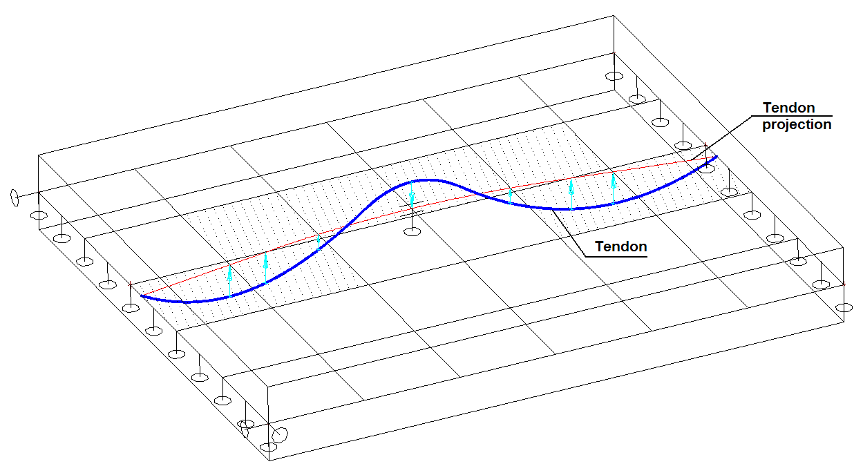
Tendon defined in 2D members
This functionality enables the user to attach internal post-tensioned tendons directly to 2D slab and shell elements. No dummy beam 1D (rib) is necessary. The mesh of the internal post-tensioned tendon and attached 2D elements can be independent.
For tendons allocated on 1D members (beams) it is possible to project the tendon perpendicularly on beam or proportionally. For tendons allocated on 2D members (slabs) only perpendicular projection is possible.
Perpendicular projection for 2D members
4.2 Real tendon input
The definition of the tendon is in menu tree: Structure>Tendons>Post-tensioned internal tendon.
Structure tree
The most suitable solution for the definition of a real post-tensioned tendon in the slab is to use the geometry input called reference line with source geometry. It means that the user defines a reference line (for instance a line from CAD program) and a source geometry. The final geometry is a composition of the reference line and source geometry. The source geometry is winded on the reference line up the total length of the source geometry.

Geometry type – Reference line + source geometry
The reference source geometry is prepared according to the design from chapter "3 Design of the prestressing". Four source geometries were prepared:
|
xC |
source geometry in the column line in the X direction |
|
xS |
source geometry in the span in the X direction |
|
yC |
source geometry in the column line in the Y direction |
|
yS |
source geometry in the span in the Y direction |
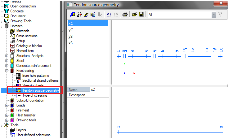
Library of source geometry
The geometries of the span and column lines in each direction (X,Y) are the same. Only the distances between each tendon are different. The tendon source geometries are the following.
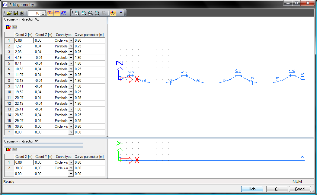
Tendon source geometry xC; xS
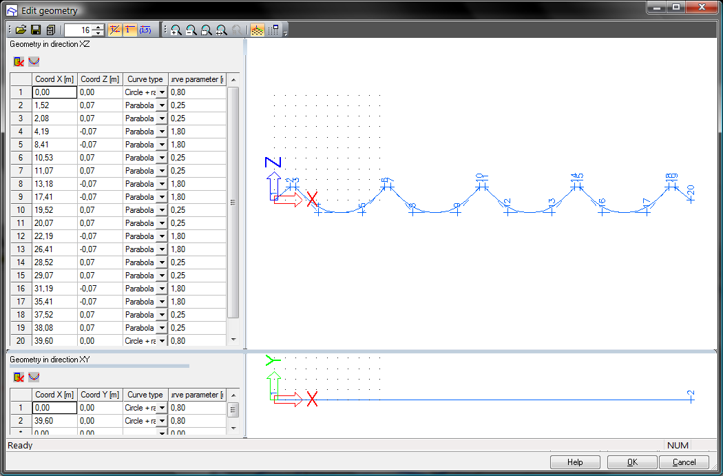
Tendon source geometry yC; yS
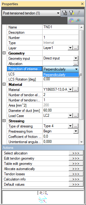
When the source geometries are defined then we can set all properties of the tendon according to the following dialogue.
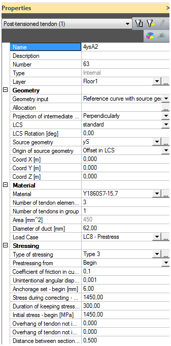
Properties of the tendon
Then program asks for the definition of the reference line. So we insert new straight line in the X axis of the column line.
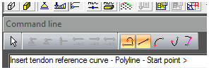
Command line
After confirming the action the program creates the post-tensioned tendon automatically.
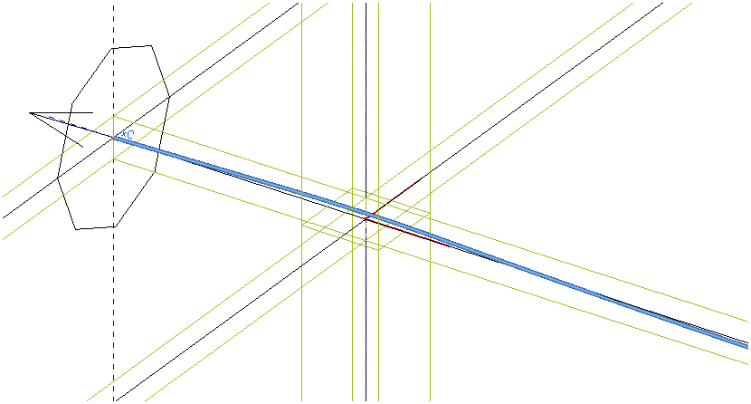
One tendon in column line
To get all tendons in correct position we can use the multicopy button to copy and offset this defined tendon to the new position.

Multicopy
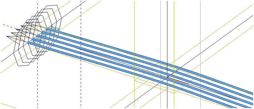
Complete column line tendons in x direction
Numbering of the tendons is the following:
4ysA2
|
4 |
number of the floor, where tendon is defined |
|
y |
direction of the tendon |
|
s |
span (s) or column (c) tendon |
|
A |
sign of the position of the column (A, B..) or the span (1,2...) |
|
2 |
number of the tendon with the same properties before |
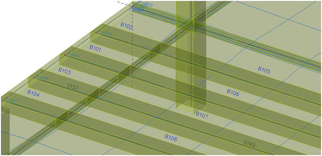
All tendons for the 4th floor are summarized in the following figure.
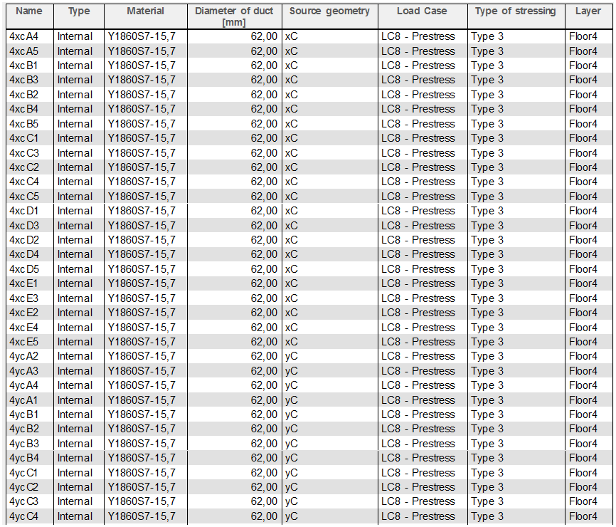
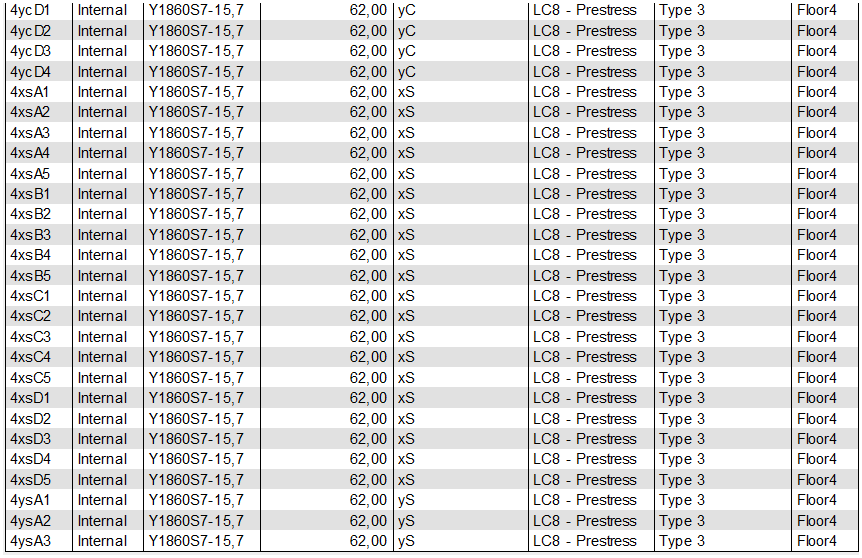
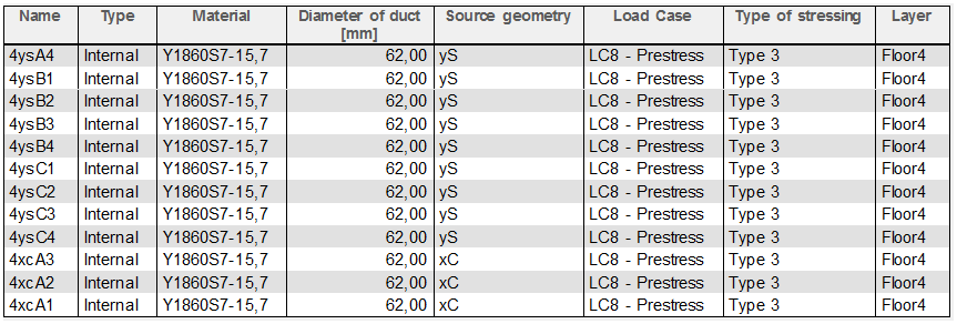
So finally when we define all tendons on the floor we get the similar figure as the following one.
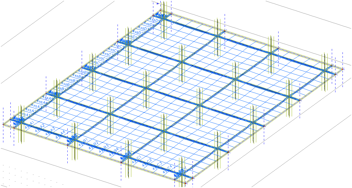
The 4th floor after definition of all tendons