Automatic calculation of the effective width of plate ribs - settings in SCIA Engineer
Plate rib settings
The following properties are a subset of the properties of 1D members of type plate rib, that are relevant for automatic calculation of effective width.
| Type rib |
plate rib (read-only) only 1D members with this property set as indicated are eligible for effective width calculation |
| Alignment |
defines the placement of the plate rib relative to its associated plate; this property affects the calculation of the contact width for the EN 1992 method
|
| Shape of rib |
defines how the effective width is distributed on each side of the beam
|
| Method |
displays the method used for the calculation of effective width for the selected beam when Shape of rib = automatic is selected (read-only) see Selection of the calculation method |
|
for int. forces |
values of effective width for internal forces |
| width left | calculated value on the left-hand side of the beam (read-only when automatic calculation is enabled) |
| width right | calculated value on the right-hand side of the beam (read-only when automatic calculation is enabled) |
| for check | values of effective width for check not available with EN 1994 method when automatic calculation is enabled |
| automatic |
available only when automatic calculation method EN 1992 is selected
|
| width left | value on the left-hand side (read-only when automatic calculation is enabled) |
| width right | value on the right-hand side (read-only when automatic calculation is enabled) |
Solver setup
The following settings are a subset of the settings in the solver setup, that are used for automatic calculation of effective width of plate ribs.
Those settings are located in the Advanced solver settings section of the solver setup.
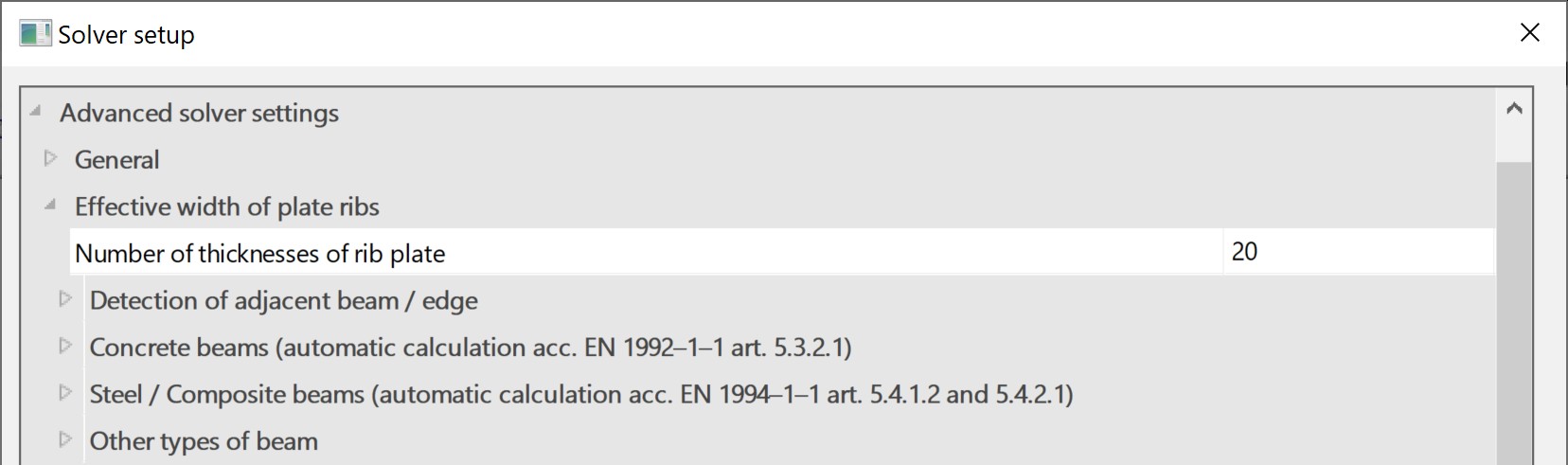
| Effective width of plate ribs | |
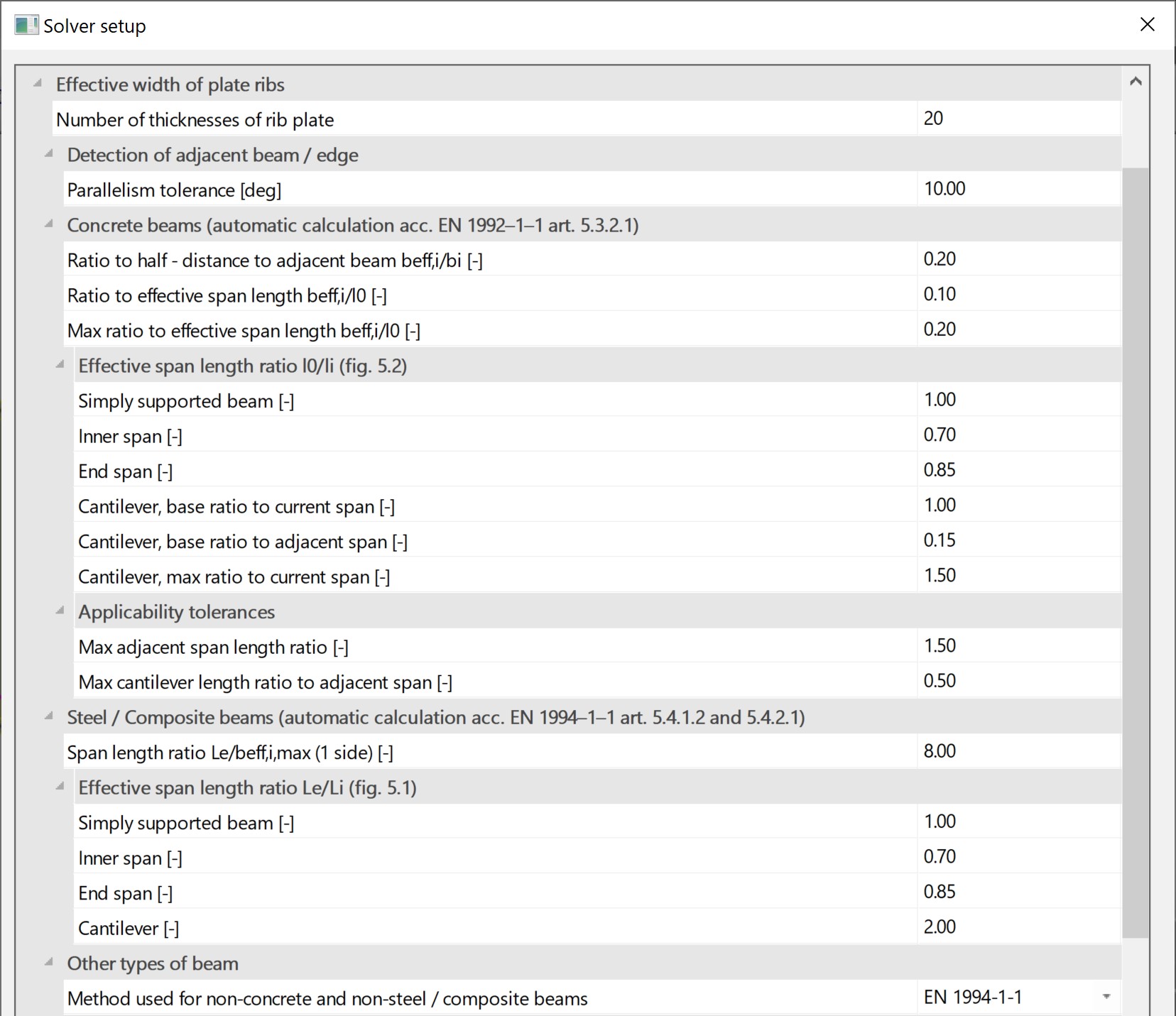
| Number of thicknesses of rib plate | coefficient to calculate the effective width as a multiple of the thickness of the linked plate (simplified, code-independent method) |
| Detection of adjacent beam / edge | |
| Parallelism tolerance | angle of tolerance used for the detection of parallel or near-parallel entities when calculating the distance from a beam to its adjacent entities |
| Concrete beams (automatic calculation acc. EN 1992-1-1 art. 5.3.2.1) | |
| Ratio to half-distance to adjacent beam beff,i/bi |
1st coefficient in formula EN 1992-1-1 (5.7a); multiplies the transverse available distance (half-distance to the adjacent beam or distance to the adjacent edge); default value = 0.2 (see EN 1992 method) |
| Ratio to effective span length beff,i/l0 |
2nd coefficient in formula EN 1992-1-1 (5.7a); multiplies the effective span length; default value = 0.1 (see EN 1992 method) |
| Max ratio to effective span length beff,i/l0 |
3rd coefficient in formula EN 1992-1-1 (5.7a); multiplies the effective span length; default value = 0.2 (see EN 1992 method) |
| Effective span length ratio l0/li (fig. 5.2) | |
| Simply supported beam |
coefficient that defines the effective span length of a simply supported beam acc. to EN 1992-1-1 fig. 5.2; default value = 1.0 (see EN 1992 method) |
| Inner span |
coefficient that defines the effective span length of an inner span of a continuous beam acc. to EN 1992-1-1 fig. 5.2; default value = 0.7 (see EN 1992 method) |
| End span |
coefficient that defines the effective span length of an end span of a continuous beam acc. to EN 1992-1-1 fig. 5.2; default value = 0.85 (see EN 1992 method) |
| Cantilever, base ratio to current span |
coefficient that defines the part related to its own length of the effective span length of a cantilever span of a continuous beam acc. to EN 1992-1-1 fig. 5.2; default value = 1.0 (see EN 1992 method) |
| Cantilever, base ratio to adjacent span |
coefficient that defines the part related to its adjacent span of the effective span length of a cantilever span of a continuous beam acc. to EN 1992-1-1 fig. 5.2; default value = 0.15 (see EN 1992 method) |
| Cantilever, max ratio to current span |
coefficient that defines the upper limit of the effective span length of a cantilever span of a continuous beam acc. to EN 1992-1-1 fig. 5.2; default value = 1.5 (see EN 1992 method) note: this coefficient is defined only in the National Annex for Germany |
| Applicability tolerances | |
| Max adjacent span length ratio |
maximum value of the span length ratio for inner and end spans of a continuous beam; this is used in the applicability check of the EN 1992 method; default value = 1.5 (see EN 1992 method) |
| Max cantilever length ratio to adjacent span |
maximum value of the span length ratio of a cantilever compared to its adjacent span; this is used in the applicability check of the EN 1992 method; default value = 1.5 (see EN 1992 method) |
| Steel/Composite beams (automatic calculation acc. EN 1994-1-1 art. 5.4.1.2 and 5.4.2.1) | |
| Span length ratio Le/beff,i,max (1 side) |
coefficient that divides the effective span length to obtain the effective width on one side of a beam; default value = 8.0 (constant a in formula, see EN 1994 method) |
| Effective span length ratio Le/Li (fig. 5.1) | |
| Simply supported beam |
coefficient that defines the effective span length of a simply supported beam acc. to EN 1994-1-1 fig. 5.1; default value = 1.0 (see EN 1994 method) |
| Inner span |
coefficient that defines the effective span length of an inner span of a continuous beam acc. to EN 1994-1-1 fig. 5.1; default value = 0.7 (see EN 1994 method) |
| End span |
coefficient that defines the effective span length of an end span of a continuous beam acc. to EN 1994-1-1 fig. 5.1; default value = 0.85 (see EN 1994 method) |
| Cantilever |
coefficient that defines the effective span length of a cantilever span of a continuous beam acc. to EN 1994-1-1 fig. 5.1; default value = 2.0 (see EN 1994 method) |
| Other types of beam | |
| Method used for non-concrete and non-steel/composite beams |
this setting defines which of the supported methods should be used for automatic calculation of effective width in case a beam is neither concrete nor composite;
|
In case the national code of the project is IBC, the settings for composite beams and other types of beams are:
| Steel/Composite beams (automatic calculation acc. AISC 360-10 I3.1a) | |
| Span length ratio Le/beff,i,max (1 side) |
coefficient that divides the effective span length to obtain the effective width on one side of a beam; default value = 8.0 (constant a in formula, (see EN 1994 method)) |
| Other types of beam | |
| Method used for non-concrete and non-steel/composite beams |
this setting defines which of the supported methods should be used for automatic calculation of effective width in case a beam is neither concrete nor composite; the options are:
|