Rib in the slab
In SCIA Engineer, aplate rib is a particular type of beam, which has a continuous connection to a plate along the entire length of the beam. The beam may be eccentric, i.e. placed above or below the plate.
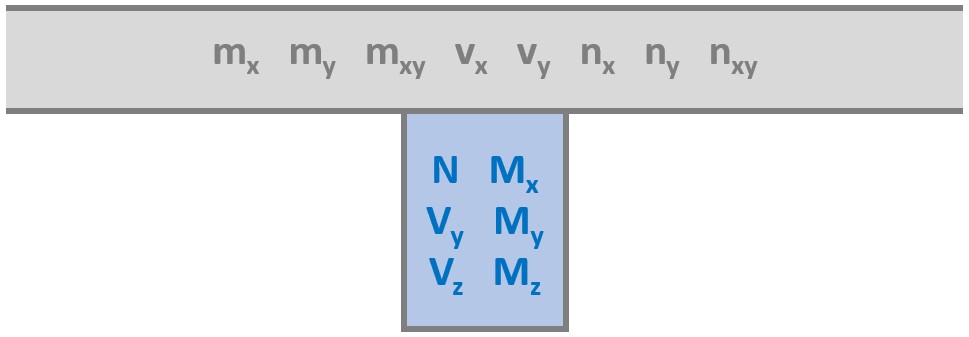
For analysis, the beam is considered as a distinct entity which fully collaborates with the plate. As a result, the analysis produces beam results in the plate rib (internal forces N, Vy, Vz, Mx, My, Mz) and plate results in the plate (internal forces mx, my, mxy, vx, vy, nx, ny, nxy).
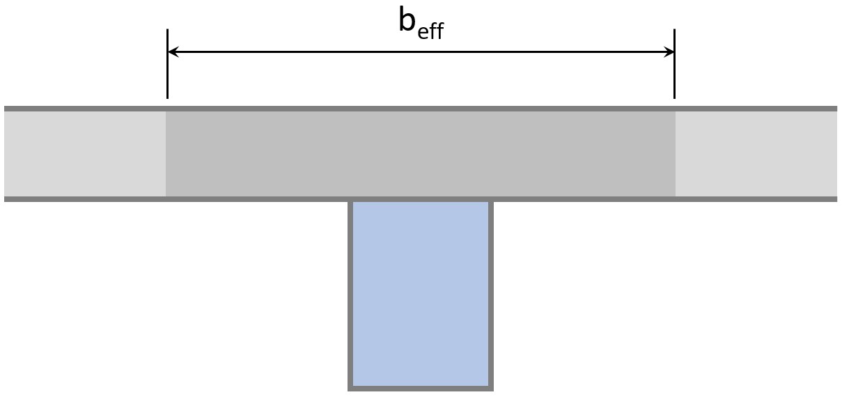
For results output and checks, the possibility exists to define the effective width beff, which enables two things:
- A T-section can be considered for checks, as a combination of the plate rib and the participating part of the linked plate
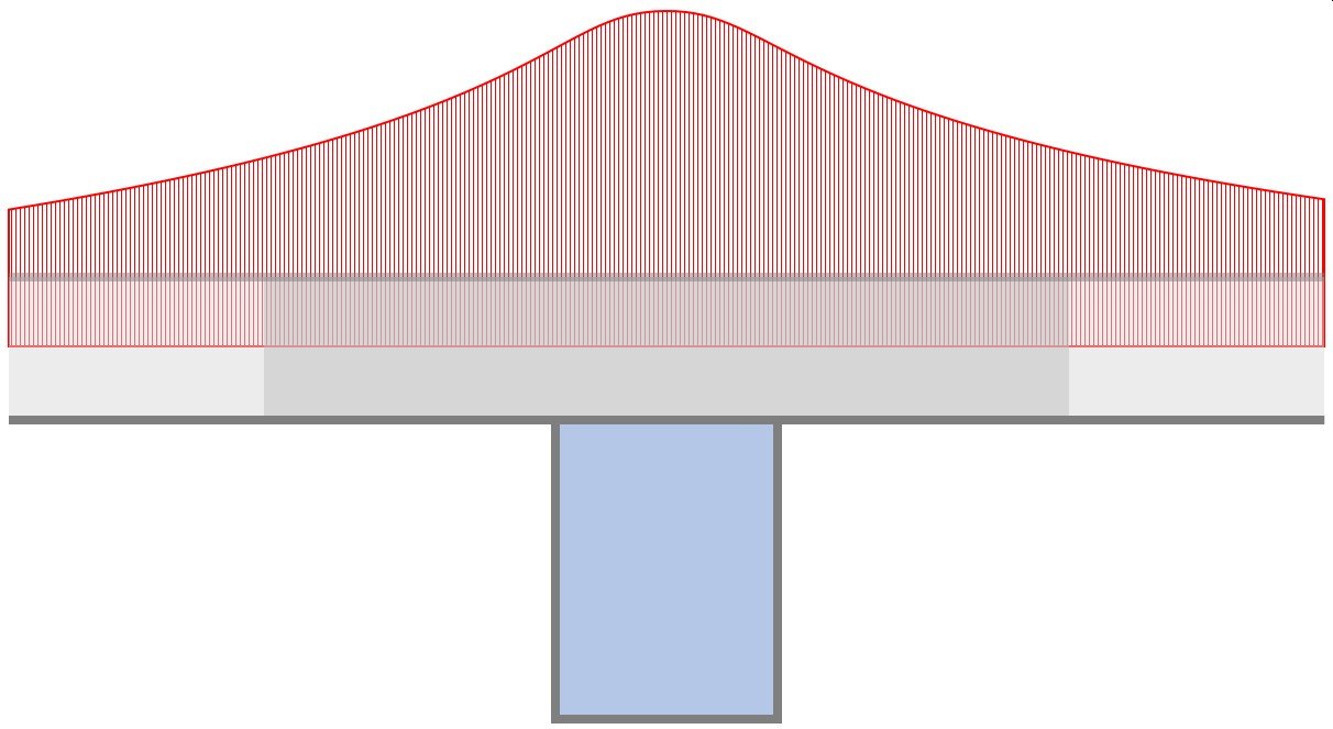
- SCIA Engineer can integrate the computed internal forces from the FEM analysis of the plate within the effective width and produce resultant beam internal forces for said T-section

Separate values of effective width are used for the calculation of internal forces and for checks. They can be defined manually or computed automatically. The latter is the default setting.
The value of effective width does not affect the behaviour of the model, as the plate is analysed as a finite element plate, not as a part of the cross-section of the beam. The effective width is considered only during post-processing, when integrating the results obtained in the plate and when calculating the strength of the cross-section during the checks.
Composite beams are a particular case: the composite analysis model allows to calculate consider the effective width of the beam in the calculation of the stiffness of the beams.
Properties of a plate rib
|
Name |
Defines the name of the rib. |
|
Type |
Informs about the type of the entity. |
|
Analysis model |
This parameter defines how the rib will be considered in the analysis. Standard = the rib of a standard cross-section Cellular beam = the rib is made of a cellular beam |
|
"special cellular beam parameters" |
If the cellular beam is selected, the dialogue allows for input of additional parameters defining the position of posts in the beam. |
|
Cross-section |
Defines the cross-section of the rib. |
|
Alignment |
Specifies the alignment of the rib: Bottom The rib is attached to the bottom of the slab. The eccentricity is calculated automatically as the sum of the half of slab thickness and the distance from the bottom slab face to the centroid of the cross-section. Top The rib is attached to the top of the slab. The eccentricity is calculated automatically as the sum of the half of slab thickness and the distance from the top slab face to the centroid of the cross-section. Centre Middle axis of the rib and the slab are coincident. The final eccentricity is equal to zero. The calculation model shows a partial doubling of stiffness of the (i) slab and (ii) the rib. |
|
Shape of rib |
There are several possible shapes of the rib
|
|
Effective width |
Specifies how the effective width is defined: Default The effective width is determined as a multiple of rib width. The multiple can be defined in Calculation, Mesh > Solver setup > Number of thicknesses of rib plate. Width The effective width is explicitly specified. The value can be input below. Number of thicknesses The effective width is determined as a multiple of the thickness. The multiple can be input below this parameter. |
|
for internal forces |
Two types of effective width can be input. Both the value are used for the modelling of composite cross-section. Value "for internal forces" is used to recalculate internal of the created composite cross-section section. Value "for check" (see below) is used to define the cross-section for the needs of design and check of reinforced cross-section. Usually, a rectangular section is attached to the slab creating the final T or L section. However, also other library cross-sections can be used to form various composite sections (e.g. steel I section + concrete reinforced plate). |
|
for check |
See above. |
|
FEM type |
Defines the type of finite element: Standard The standard 1D finite element is used. The element can transfer both moments, axial and shear forces. Axial force only Truss finite element is applied. This element is capable of transferring the axial force only. |
|
Buckling and relative lengths |
Can be used to specify buckling lengths. |
|
Layer |
|
|
2D member |
Informs about the "associated" slab. |
Geometry parameters
These parameters are shown in the property window of an already defined rib. They are not displayed when a new rib is being defined.
|
Length |
Tells the length of the rib. |
|
Shape |
Informs about the shape of the entity. |
|
Specifies the starting node of the rib. This parameter can be edited, which would affect the location and length of the rib. Before editing, you must find the name of node you want to use as the beginning node. |
|
|
End node |
Similar to above. Defines the end-node of the rib. |
Structural model
This set of parameters can be used to specify the structural model of the rib. The structural model is important especially if drawings and/or impressive pictures of the structure are to be made.
See chapter Geometry > Structural model > Parameters of structural model for more details.