Capacity check Theoretical background
The capacity check for fibre reinforced concrete is based on the calculation of the resistance of cross-section with the current fibre dosage and standard reinforcement and comparison of it with acting load to get equilibrium of forces.
The calculation precognitions for finding plane of equilibrium of steel fibre concrete with reinforcement are taken from Figure R.4 - Determining stresses and strains for steel fibre reinforced concrete from [1] DAfStb Guideline "Steel fibre reinforced concrete".
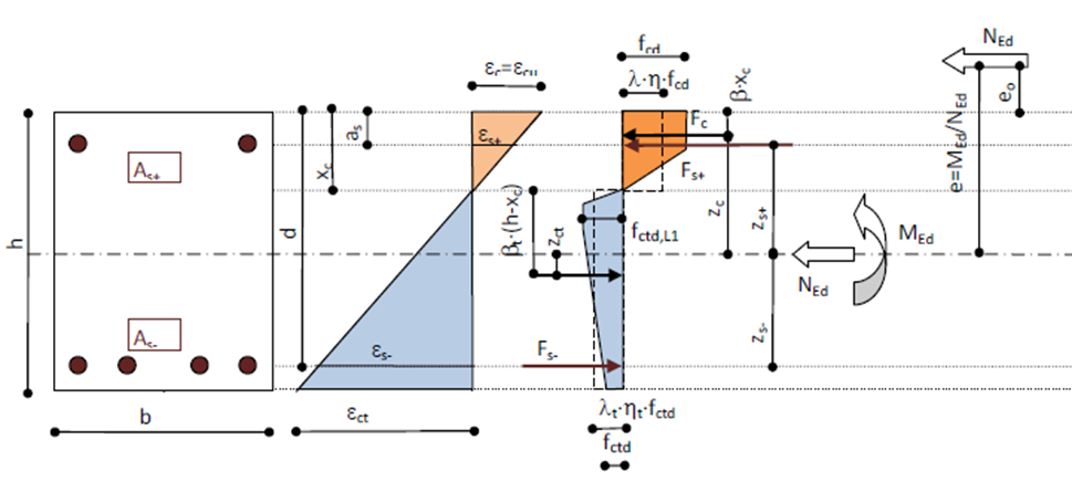
The following conditions of equilibrium must be fulfilled.
Fc+Fct+Fs++Fs-+NEd =0
Fc. zc + Fct.zct + Fs+. zs++Fs-.zs- + MEd =0
Following procedure is used for calculation of the Capacity check for fibre reinforced concrete.
- Definition of the input values for calculation
- The calculation of the height of the compression zone
- Calculation of the reinforcement material parameters
- Calculation of the concrete material parameters
- Calculation of the area of reinforcement
- Calculation of the diameter of reinforcement
- Calculation of the cover of reinforcement
- Calculation of the lever arm of forces in reinforcement from the centre of gravity
- Calculation of the effective depth of the cross-section
- Calculation of the centre to centre distance from more compressive edge
- Calculation of the balanced parameters of the cross-section
- Calculation of the fibre concrete material parameters in tension
- Estimation of the reinforcement stress for calculation of the compression zone
- Calculation of the balanced normal force
- Calculation of the height of the compression zone
- The calculation of the resistance of the cross-section
- Calculation of the inner lever arm for concrete and reinforcement from centre of gravity
- Calculation of the stress in the reinforcement according to height of the compression zone
- Calculation of the resistance
- Calculation of the unity check
The calculation of the height of the compression zone
Calculation of the reinforcement material parameters
The reinforcement material parameters are calculated independently for upper and lower surface, they can be generally different.
fyd+(-) = fyk+(-) / γs
Es+(-)
where
| fyk+(-) |
Characteristic yield strength of reinforcement, different according Type of calculated reinforcement:
fyk+(-) = ∑(As+(-),i ∙ fyk+(-),i) / ∑(As+(-),i) where
|
||||
| γs |
Partial factor for reinforcing steel, national dependent value in EN 1992-1-1, §2.4.2.4(1), for details see "National annexes theoretical background". |
||||
| Es+(-) |
Modulus of elasticity of reinforcement, different according Type of calculated reinforcement:
Es+(-) = ∑(As+(-),i ∙ E+(-),i) / ∑(As+(-),i) where
|
Calculation of the concrete material parameters
Calculation of the design value of compressive concrete strength
fcd = αcc ∙ fck / γC
where
| αcc |
The coefficient taking account of long term effects on the compressive strength and of unfavourable effects resulting from the way the load is applied, national dependent value in EN 1992-1-1, §3.1.6(1)P, for details see "National annexes theoretical background". |
| fck |
Characteristic compressive cylinder strength of concrete at 28 days |
| γC | Partial factor for concrete, national dependent value in EN 1992-1-1, §2.4.2.4(1), for details see "National annexes theoretical background". |
Calculation of the strains for concrete stress-strain diagram
Proper strains are used according selected type of stress-strain diagram
- Bilinear - εc3, εcu3
- Parabolic - εc2, εcu2
Calculation of the extra rotation point
The extra rotation point is used in the calculation
HeightRatio = 1 - (εc2(3) / εcu2(3))
StrainRatio = (εc2(3) / εcu2(3)
Calculation of the strength reduction factor for strength of concrete and position of concrete compressive force
For bilinear stress-strain diagram
η = 1 - (εc3 / εcu3) / 2
β = 1 - (εcu32 / 2 - εc32 / 6) / (εcu32 - εcu3 ∙ εc3 / 2)
For parabolic stress-strain diagram
η = 1 - {εc2 / [(n + 1) ∙ εcu2]}
β = 1 - {εcu22 / 2 - εc22 / [(n + 1) ∙ (n + 2)]} / [εcu22 - εcu2 ∙ εc2 / (n + 1)]
where
| εc2(3) |
The strain at the reaching the maximum strength for parabolic (bilinear) stress-strain diagram according to Table 3.1 from EN 1992-1-1 |
| εcu2(3) |
The ultimate strain for parabolic (bilinear) stress-strain diagram according to Table 3.1 from EN 1992-1-1 |
| n | The exponent for parabolic stress-strain diagram according to Table 3.1 from EN 1992-1-1 |
Calculation of the area of reinforcement
The area of reinforcement is calculated as the sum of all reinforcement for upper and lower surface on the 2D element
As+(-) = ∑As+(-),i
Calculation of the diameter of reinforcement
The diameters of reinforcement bars are calculated independently for upper and lower surface, they can be different.
Different procedure is used according Type of calculated reinforcement:
- Nearest - The diameter of reinforcement bar, which is the nearest to the upper (lower) surface, is used as ds+(-)
- Average - The average diameter of all reinforcement bars which are on upper (lower) surface, is used as ds+(-)
ds+(-) = ∑(As+(-),i ∙ ds+(-),i) / ∑(As+(-),i)
where
| As+(-),i |
The area of i-th reinforcement bar on the upper (lower) surface |
| ds+(-),i |
The diameter of reinforcement of i-th bar on the upper (lower) surface |
Calculation of the cover of reinforcement
The cover of reinforcement is calculated independently for upper and lower surface, they can be different.
Different procedure is used according Type of calculated reinforcement:
- Nearest - The cover of reinforcement bar, which is the nearest to the lower (-) and upper (+) surface
c- = 0.5 ∙ h + Y(z)-
c+ = 0.5 ∙ h - Y(z)+
where
| h |
Thickness of 2D element |
| Y(z)- |
Y-coordinate (vertical) of the reinforcement which is the nearest to the lower surface |
| Y(z)+ |
Y-coordinate (vertical) of the reinforcement which is the nearest to the upper surface |
- Average - The average diameter of all reinforcement bars which are on lower (upper) surface
c-(+) = 0.5 ∙ h - zs-(+)
where
| h |
Thickness of 2D element |
| zs-(+) |
The lever arm of forces in reinforcement from the centre of gravity |
Calculation of the lever arm of forces in reinforcement from the centre of gravity
The lever arms of forces in reinforcement from the centre of gravity are calculated independently for upper and lower surface, they can be different.
Different procedure is used according Type of calculated reinforcement:
- Nearest - The lever arms of forces in reinforcement, which is the nearest to the lower (-) and upper (+) surface
zs- = -0.5 ∙ h + c- + 0.5 ∙ ds-
zs+ = 0.5 ∙ h - c+ - 0.5 ∙ ds+
where
| h |
Thickness of 2D element |
| c-(+) |
The cover to the lower (upper) reinforcement |
| ds-(+) |
The diameter of lower (upper) reinforcement |
- Average - The average diameter of all reinforcement bars which are on upper (lower) surface
zs+(-) = ∑(As+(-),i ∙ zs+(-),i) / ∑(As+(-),i)
where
| As+(-),i |
The area of i-th reinforcement bar on the upper (lower) surface |
| zs+(-),i |
The Y-coordinate (vertical) of i-th bar of reinforcement on the upper (lower) surface |
Calculation of the effective depth of the cross-section
The effective depth of cross-section is calculated from cover and diameter of reinforcement
d = h - c-(+) - 0.5 ∙ ds-(+)
where
| h |
Thickness of 2D element |
| c-(+) |
The cover to the lower (upper) reinforcement |
| ds-(+) |
The diameter of lower (upper) reinforcement |
The decision if lower or upper reinforcement characteristics are used is based on the value of bending moment (positive → lower reinforcement, negative → upper reinforcement.
For fibre concrete without longitudinal reinforcement (As,sum = 0 mm2) is d = h.
Calculation of the centre to centre distance from more compressive edge
The centre to centre distance from more compressive edge is calculated from cover and diameter of reinforcement
as = c-(+) + 0.5 ∙ ds-(+)
where
| c-(+) |
The cover to the lower (upper) reinforcement |
| ds-(+) |
The diameter of lower (upper) reinforcement |
The decision if lower or upper reinforcement characteristics are used is based on the value of bending moment (positive → lower reinforcement, negative → upper reinforcement.
For fibre concrete without longitudinal reinforcement (As,sum = 0 mm2) is as = 0 mm.
Calculation of the balanced parameters of the cross-section
The balanced parameters ξbal for balanced depth of compression zone and depth of the compression zones xbal are calculated as follows
The decision if εcu2 or εcu3 are used is based on the type of stress-strain diagram (εcu2→ parabolic, εcu3→ bilinear).
The decision if lower or upper reinforcement characteristics are used is based on the value of bending moment. For more tensile edge: positive → lower reinforcement, negative → upper reinforcement. For less tensile edge: positive → upper reinforcement, negative → lower reinforcement.
- The balanced parameter for more tensile edge when cross-section is in tension
ξbal1,t = εcu2(3) / [εcu2(3) + (fyd-(+) / Es-(+))]
- The balanced parameter for more tensile edge when cross-section is in compression
ξbal1,c = εcu2(3) / [εcu2(3) - (fyd-(+) / Es-(+))]
- The balanced parameter for less tensile edge when cross-section is in tension
ξbal2,t = εcu2(3) / [εcu2(3) - (fyd+(-) / Es+(-))]
- The balanced parameter for less tensile edge when cross-section is in compression
ξbal2,c = εcu2(3) / [εcu2(3) + (fyd+(-) / Es+(-))]
The balanced depth of compression zone is than calculated as follows
- For more tensile edge
xbal1 = ξbal1,t(c) ∙ d
- For less tensile edge
xbal2 = ξbal2,t(c) ∙ d
Calculation of the fibre concrete material parameters in tension
The fibre concrete material parameters are calculated according the recommendations from the Entwurf DAfStb Guideline for Steel fibre reinforced concrete.
The design value of tensile concrete strength
For calculation procedure of ffctd,L1 and ffctd,L2 see the chapter "Design values" in "Materials theoretical background".
The balanced depth of compression zone for fibre concrete
ξfbal,t = εcu2(3) / (εcu2(3) + εfct_L2)
where
| εfct_L2 |
The strain in the fibre reinforced concrete at reaching residual tensile strength in the performance class 2 |
The tensile strain and stress in fibre concrete
The calculation of stress and strain in fibre concrete in divided to two branches according the ratio of xc / d with ξfbal,t.
- when xc / d ≥ ξfbal,t
εfct = εcu2(3) ∙ (d - xc) / xc
εfcc = εcu2(3)
IF ffctd,L2 < ffctd,L1
THEN ffctd = ffctd,L2 + (ffctd,L1 - ffctd,L2) ∙ (εfct_L2 - εfct) / (εfct_L2 - εfct_L12)
ELSE ffctd = ffctd,L1 + (ffctd,L2 - ffctd,L1) ∙ (εfct - εfct_L12) / (εfct_L2 - εfct_L12)
- when xc / d < ξfbal,t
εfct = εfct_L2
εfcc = εfct_L2 ∙ xc/ (d - xc)
where
| εfct_L12 |
The strain in the fibre reinforced concrete at starting descending branch of residual tensile strength in performance class 1 |
The reduction factor for tensile strength of concrete and position of concrete tensile force
Two support values are calculated
Afct = 0.5 ∙ (εfct_L12 - εfct_L11 + εfct) + 0.5 ∙ (ffctd / ffctd,L1) ∙ (εfct - εfct_L12)
Sfct = εfct_L112 / 3 + (εfct_L12 - εfct_L11)2 / 2 + [(ffctd,L1 - ffctd) / ffctd,L1] ∙ [(εfct - εfct_L12) / 2] ∙ [(εfct - εfct_L12) / 3 + εfct_L12] + (ffctd / ffctd,L1) ∙ (εfct - εfct_L12) ∙ [(εfct - εfct_L12) / 2 + εfct_L12]
The reduction factors are than calculated as follows
ηft = Afct / εfct
βft = Sfct / (Afct / εfct)
λft = 1.0
Estimation of the reinforcement stress for calculation of the compression zone
Stress in upper and lower reinforcement is estimated for the calculation of first iteration as "starting point". The stresses are generally set to yield strength of reinforcement.
- For only compression load
IF mEd = 0
THEN σs+(-) = max(-εc2(3) ∙ Es+(-); -fyd+(-))
ELSE σs+(-) = -fyd+(-)
- For only tension load
σs+(-) = -fyd+(-)
- For compression and tension load together
IF mEd ≥ 0
THEN σs+ = -fyd+ and σs- = fyd-
ELSE σs+ = fyd+ and σs- = -fyd-
Calculation of the balanced normal force
The balanced normal force nRd,bal is force in the cross-section, when balanced state is adjusted.
nRd,bal = - xbal1 ∙ λ ∙ b ∙ η ∙ fcd + (h - xbal1) ∙ λft ∙b ∙ ηft ∙ fctd,L1 + As+ ∙ σs+ + As- ∙ fyd-
Calculation of the height of compression zone
Three possibilities for calculation of the height of compression zone are available
- nRd method (height of compression from force)
xc = (-nEd + λft ∙ b ∙ h ∙ ηft ∙ fctd,L1 + As- ∙ σs- + As+ ∙ σs+) / (λ ∙ b ∙ η ∙ fcd + λft ∙ b ∙ ηft ∙ fctd,L1)
- mRd method (height of compression from moment)
βtin = 1 - βft
A = λ ∙ b ∙ η ∙ fcd ∙ β + λft ∙ b ∙ ηft ∙ fctd,L1 ∙ βtin
B = -λ ∙ b ∙ η ∙ fcd ∙ 0,5 ∙ h - λft ∙ b ∙ ηft ∙ fctd,L1 ∙ h ∙ (2 ∙ βtin - 0,5)
C = |mEd| + As- ∙ σs- ∙ zs- + As+ ∙ σs+ ∙ zs+ - λft ∙ b ∙ ηft ∙fctd,L1 ∙ h2 ∙ (0,5 - βtin)
D = B2 - 4 ∙ A ∙ C
if D ≥ 0
THEN xc = (-B - √D) / (2 ∙ A)
ELSE xc = -999 and error message is shown
- nRd/mRd method (height of compression from eccentricity)
eccentricity: e = -|mEd / nEd|
βtin = 1 - βft
A = λ ∙ b ∙ η ∙ fcd ∙ β + λft ∙ b ∙ ηft ∙ fctd,L1 ∙ βtin
B = -λ ∙ b ∙ η ∙ fcd ∙ (0,5 ∙ h - e) - λft ∙ b ∙ ηft ∙ fctd,L1 ∙ h ∙ (2 ∙ βtin - 0,5 ∙ h + e)
C = As- ∙ σs- ∙ (zs- - e) + As+ ∙ σs+ ∙ (zs+ - e) - λft ∙ b ∙ ηft ∙fctd,L1 ∙ h2 ∙ (0,5 ∙ h - βtin ∙ h - e)
D = B2 - 4 ∙ A ∙ C
if D ≥ 0
THEN xc = (-B -(+) √D) / (2 ∙ A) (- when e < 0; + when e > 0)
ELSE xc = -999 and error message is shown
The calculation of the resistance of the cross-section
Calculation of the inner lever arm for concrete and reinforcement from centre of gravity
Inner level arm of compressive forces in concrete from centre of gravity
IF mEd ≥ 0
THEN zcc = 0,5 ∙ h - β ∙ xc
ELSE zcc = -0,5 ∙ h + β ∙ xc
Inner level arm of tensile forces in concrete from centre of gravity
IF mEd ≥ 0
THEN zct = - xc - (h - xc) ∙ βft + 0,5 ∙ h
ELSE zct = + xc + (h - xc) ∙ βft - 0,5 ∙ h
IF xc < 0, THAN zct = 0
Calculation of the stress in the reinforcement according to height of the compression zone
Three possible states for recognition of stress in reinforcement, based on comparison of xc with d and as.
- xc ≤ d and xc ≥ as
IF mEd ≥ 0
THEN σs+ = -fyd+; σs- = fyd-
ELSE σs+ = fyd+; σs- = -fyd-
- xc < as
σs+ = fyd+; σs- = fyd-
- xc > d
IF mEd = 0
THEN σs+ = max(-εc2(3) ∙ Es+, -fyd+) ; σs- = max(-εc2(3) ∙ Es-, -fyd-)
ELSE σs+ = -fyd+; σs- = -fyd-
Calculation of the resistance
The resistance of the cross-section is based on calculation of forces in compressive and tensile concrete and in reinforcement and than these forces are multiplicative by inner level arms to obtain final resistances.
- Concrete compressive area
Acc = xc ∙ b
- Concrete tensile area
Act = (h - xc) ∙ b
- Minimal concrete stress
σcc = -fcd
- Maximal concrete stress (tension)
σct = fctd,L1
- Compressive force in concrete
Fcc = Acc ∙ η ∙ σcc
- Tensile force in concrete
IF xc > 0
THEN Fct = Act ∙ ηft ∙ σct
ELSE Fct = Act ∙ fctd,L2
- Forces in lower (-) and upper (+) reinforcement
Fs-(+) = As-(+) ∙ σs-(+)
- Resistances of the cross-section
nRd = Fcc + Fct + Fs- + Fs+
mRd = - Fcc ∙zcc - Fct ∙ zct - Fs- ∙zs- - Fs+ ∙ zs+
The calculation of the unity check
Final unity check is calculated according selected type of method for calculation
- nRd method
UC = mEd / mRd
- mRd method
UC = nEd / nRd
- nRd/mRd method
UC = max(mEd / mRd, nEd / nRd, (nEd2 + mEd2)0,5 / (nRd2 + mRd2)0,5)
Final value of unity check can be drawn in 3D scene in SCIA Engineer.
Check of the compression strut
On addition to capacity check is the check of compression strut. The internal forces which are calculated in the direction of the concrete strut have to be also checked. The internal forces have to be carried by concrete in compression.
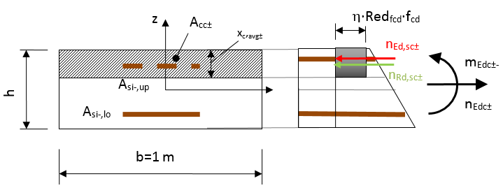
The depth of the compression zone is calculated for each surface as average values from user defined reinforcement for both directions
xc,avg± = 0,5 ∙ (xc,1± + xc,2±)
where
| xc,1± |
Depth of the compression zone calculated from user defined reinforcement in the first direction |
| xc,2± |
Depth of the compression zone calculated from user defined reinforcement in the second direction |
Design value of resistance of concrete compressive strut is calculated according formula
nRd,sc± = -Acc± ∙ η ∙ Redfcd ∙ fcd
where
| Acc± |
The area of the compression concrete at upper (lower) surface Acc± = xc,avg± ∙ 1 m |
| η |
The coefficient for reduction design compressive strength of the concrete from concrete setup |
| Redfcd | The coefficient for reduction strength of the concrete in compressive concrete strut from concrete setup |
| fcd | The design compressive strength of concrete |
Unity check is than calculated as follows
UCsc = max(nEd,sc+ / nRd,sc+, nEd,sc- / nRd,sc-)
The value of Unity check for compression strut is also part of capacity check UC
UC = max(UCcapacity, UCsc)