Crack width theoretical background
The crack width for slabs with standard reinforcement
When standard reinforcement exists, the crack width is calculated according equation R.7.8 [1] DAfStb Guideline "Steel fibre reinforced concrete":
wk = sr,max ∙ (εfsm - εcm)
where
| sr,max |
The maximum final crack spacing. |
| (εfsm - εcm) |
The difference between mean strains in concrete and reinforcement in case of steel fibre reinforced concrete. |
The maximum final crack spacing
sr,max = (1 - αf) ∙ ϕs / (3,6 ∙ ρp,eff) ≤ (1 - αf) ∙ (σs ∙ ϕs) / (3,6 ∙ fct,eff)
where
| αf |
The coefficient for fibre reinforcement concrete αf = ffctR,s / fctm |
| ϕs |
Averaged diameter of reinforcement, see the chapter Calculation of the diameter of reinforcement in "Capacity check theoretical background" |
| ρp,eff |
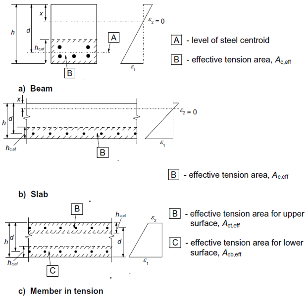
The effective reinforcement ratio obtained from the equation 7.10 from [2] EN1992-1-1 ρp,eff = As / Ac,eff |
| fct,eff | The effective tensile strength of concrete |
The difference between mean strains
The difference is calculated according equation R.7.9
(εfsm - εcm) = ((1 - αf) ∙ (σs - 0,4 ∙ fct,eff / ρp,eff)) / Es ≥ 0,6 ∙ (1 - αf) ∙ σs / Es
where
| αf |
The coefficient for fibre reinforcement concrete αf = ffctR,s / fctm |
||||
| ϕs |
Averaged diameter of reinforcement, see the chapter Calculation of the diameter of reinforcement in "Capacity check theoretical background" |
||||
| ρp,eff |
The effective reinforcement ratio obtained from the equation 7.10 from [2] EN1992-1-1 ρp,eff = As / Ac,eff where
|
||||
| fct,eff | The effective tensile strength of concrete | ||||
| εfsm | The mean strain in the reinforcement in steel fibre reinforced concrete for the relevant combination of actions taking tension stiffening into account | ||||
| εcm | The mean strain in concrete between cracks | ||||
| σs | The reinforcement stress in the crack without taking into account the fibre effect. Maximal value of tensile stress of the reinforcement inside area Ac,eff. | ||||
| Es | Modulus of elasticity of standard reinforcement |
The crack width for slabs without standard reinforcement
When standard reinforcement does not exists on selected 2D member, the crack width is calculated according equation R.7.11 [1] DAfStb Guideline "Steel fibre reinforced concrete":
wk = sfw ∙ εfct
where
| sfw |
= 140 mm |
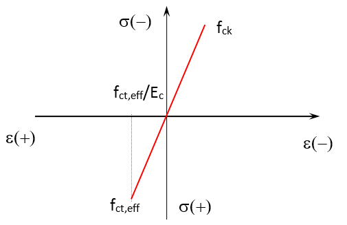
| εfct |
The strain in the steel fibre reinforced concrete, where stress-strain diagram is same as for standard concrete with linear effective branch in tension |
Recalculation of internal forces and reinforcement areas for Crack width
The crack width are calculated in the direction of principal forces. Therefore is necessary to recalculate basic internal forces and the reinforcement areas to the principal directions.
Normal stresses per directions and surfaces
Normal stresses per each direction of member LCS and for upper(lower) surface are calculated.
σx,up(lo) = nx / (h ∙ 1m) -(+) mx / (1/6 ∙ h2 ∙ 1m)
σy,up(lo) = ny / (h ∙ 1m) -(+) my / (1/6 ∙ h2 ∙ 1m)
σxy,up(lo) = nxy / (h ∙ 1m) -(+) mxy / (1/6 ∙ h2 ∙ 1m)
where
| nx(y) |
Normal force in centre of mesh element in x(y) direction |
| mx(y) |
Bending moment in centre of the mesh element in x(y) direction |
| nxy | Membrane shear force in centre of the mesh element |
| mxy | Twisting moment in centre of the mesh element |
| h | Thickness of the 2D member |
Principal stresses for both surfaces
σ1,up(lo) = (σx,up(lo) + σy,up(lo)) / 2 + 1/2 ∙ √(σx,up(lo) - σy,up(lo))2 + 4 ∙ σxy,up(lo)2)
σ2,up(lo) = (σx,up(lo) + σy,up(lo)) / 2 - 1/2 ∙ √(σx,up(lo) - σy,up(lo))2 + 4 ∙ σxy,up(lo)2)
and σ1,up(lo) is greater than σ2,up(lo)
Angles of principal stresses from y axis for both surfaces
First direction
when (σx,up(lo) - σy,up(lo)) > 0
ασ1,up(lo) = arctg(2 ∙ σxy,up(lo) / (σx,up(lo) - σy,up(lo))) / 2
when (σx,up(lo) - σy,up(lo)) < 0
ασ1,up(lo) = arctg(2 ∙ σxy,up(lo) / (σx,up(lo) - σy,up(lo))) / 2 - 90 °
when (σx,up(lo) - σy,up(lo)) = 0
- when σxy,up(lo) = 0
ασ1,up(lo) = 0
- when σxy,up(lo) < 0
ασ1,up(lo) = -45 °
- when σxy,up(lo) > 0
ασ1,up(lo) = 45 °
Second direction
ασ2,up(lo) = ασ2,up(lo) + 90 °
Recalculation of areas of reinforcement to direction of principal stresses
When standard reinforcement 2D mesh is defined, than is necessary to recalculate its area to the direction of principal stress.
As(ασ) = ∑(As,i ∙ cos(ασ - αs,i))
where
Recalculation of the internal forces for the crack width
mup(lo) = mx ∙ cos(ασ,up(lo))2 + my ∙ sin(ασ,up(lo))2 + mxy ∙ sin(2 ∙ ασ,up(lo))
nup(lo) = nx ∙ cos(ασ,up(lo))2 + ny ∙ sin(ασ,up(lo))2 + nxy ∙ sin(2 ∙ ασ,up(lo))
The recalculation is done four times in total. Once per direction and surface.
Limit value of crack width
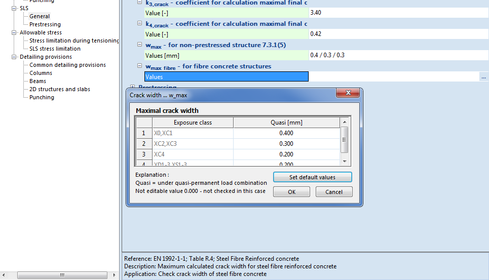
When steel fibre reinforcement concrete contains standard reinforcement 2D meshes, than is the limit value of crack width wlim taken same as for standard concrete according clause 7.3.1(5) from [2] EN1992-1-1
When steel fibre reinforcement concrete does not contain standard reinforcement, than is the limit value of crack width wlim taken from the National annex manager in group SLS - General. Where is new item - wmax_fibre according the [1] DAfStb Guideline "Steel fibre reinforced concrete"in table R.4.