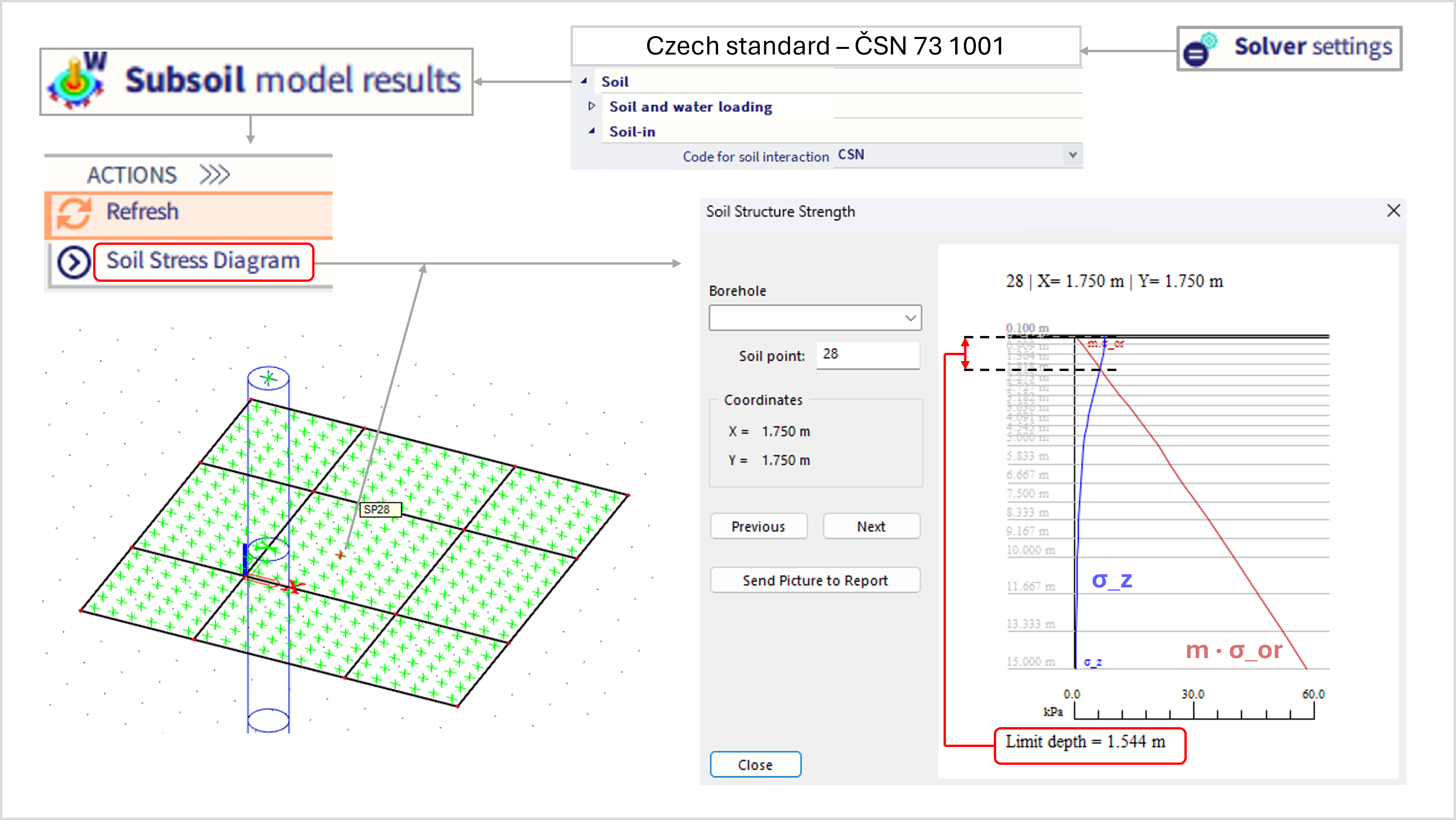
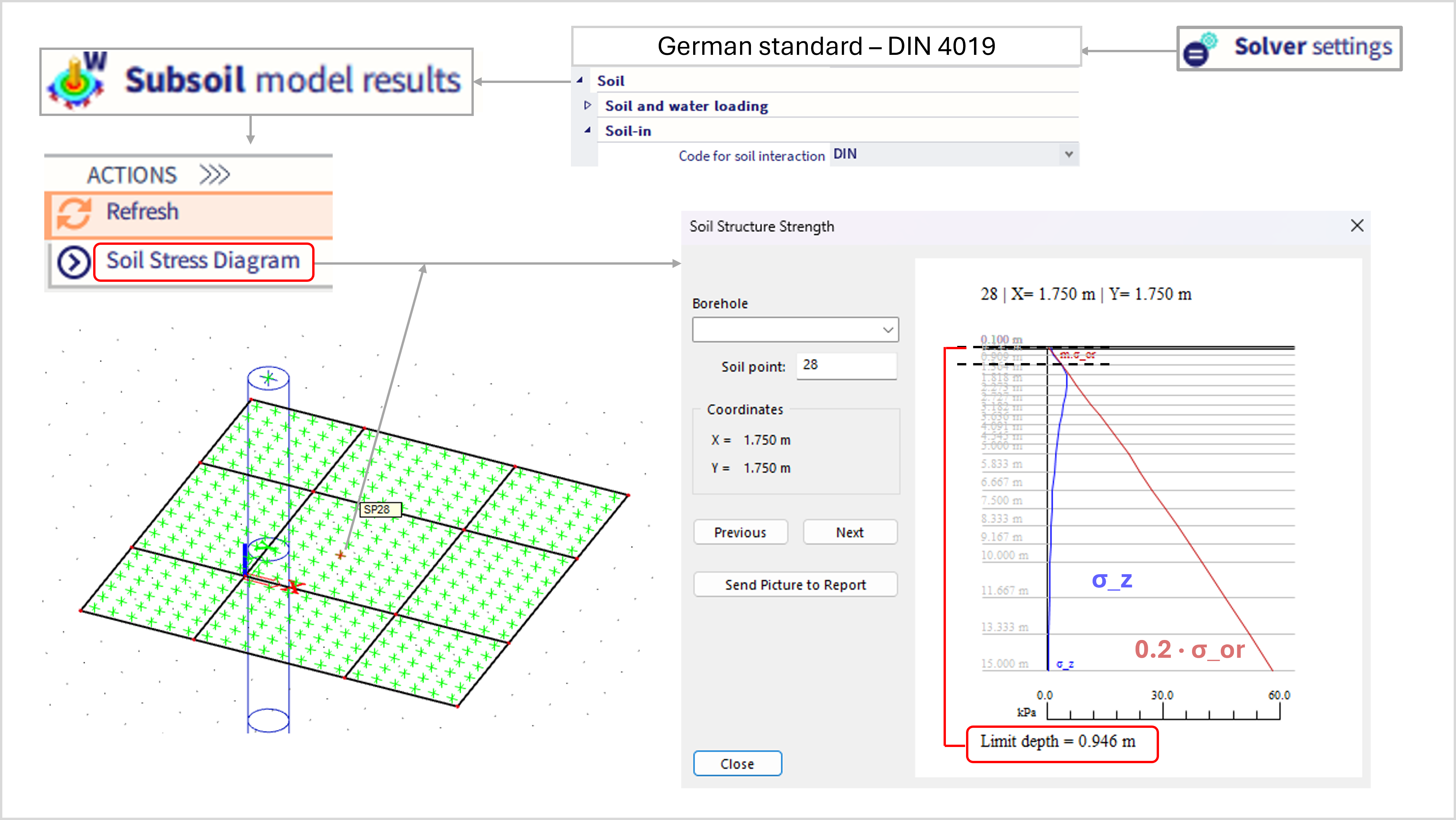
Subsoil - Soilin - Codes for soil interaction: CSN, EN and DIN differences
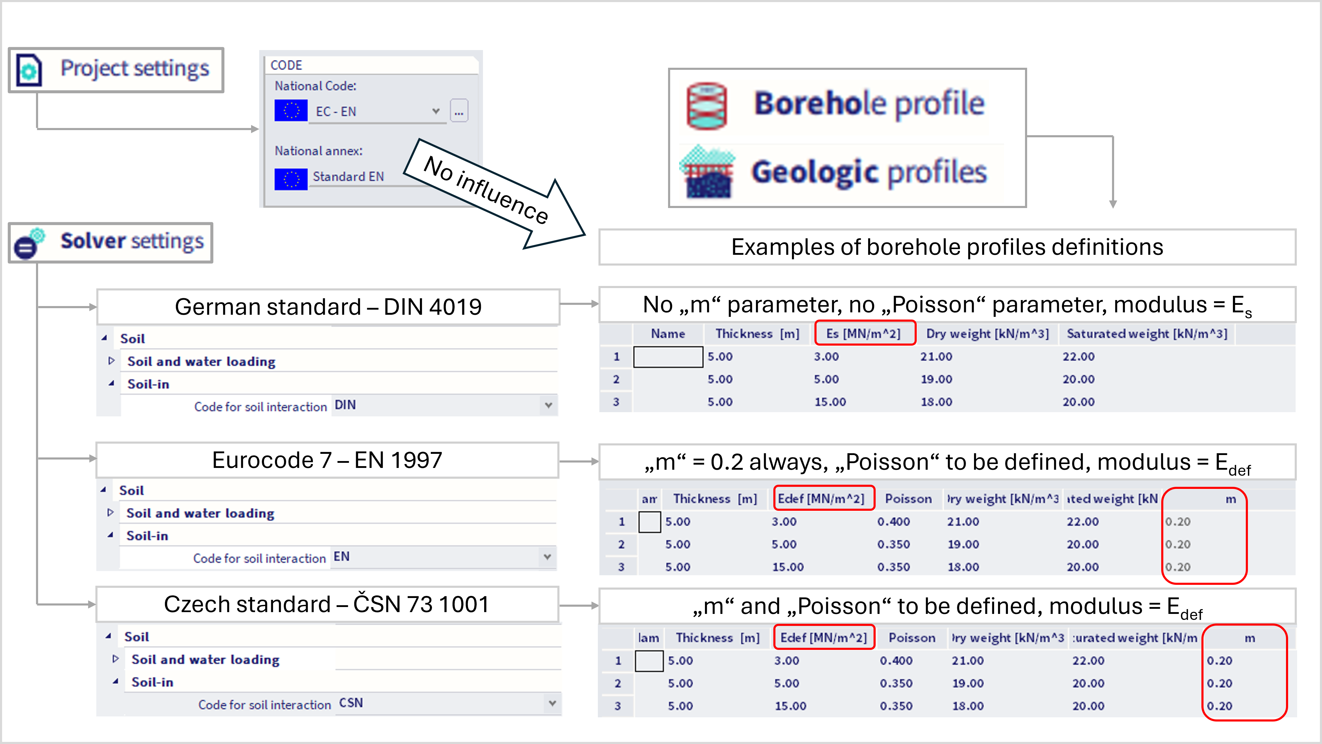
This chapter provides more detailed information about the differences caused by solver setting "code for soil interaction". This setting has also influence on the geologic profile definition, as also summarized in the figure below:
Figure 1.1: Geologic profile definition:
In more detail, the differences are explained below.
Physical model of soil based on ČSN 73 1001
The calculation model of subsoil is defined in art 116 – 122 of the standard ČSN 73 1001. There is no sense in rewriting the related paragraphs. Comments on the provisions within the context of their application for the interaction of buildings with soil environment is provided in this chapter.
The standard stipulates in page 33 the formula for the calculation of settlement s of the subsoil surface:
Equation 2.1:

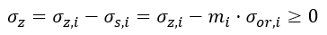
where σz,i is the vertical axial component of stress in an elastic homogenous infinite half space (or stratum), σor,i is the analogous component of the original geostatic stress, mi is the correction coefficient for surcharge loading (coefficient of structural strength), σs,iis the structural strength (σs,i=mi· σor,i) and n is the number of strata with thicknesses hi and constrained (oedometric) modulus Eoed,iin which the effective stress is non-negative:
Equation 2.2:
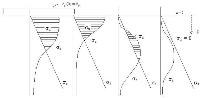
Zero deformation is assigned to regions where the effective stress is negative. This represents mainly larger depths where the subsoil does not deform any more. The condition of zero effective stress then determines what is termed the depth of the deformed subsoil zone. The situation is, however, a bit more complex in regions outside of the foundation base. Even though the magnitude of the vertical axial component σzis zero on the surface, it increases in deeper strata due to the effect of shear distribution - see the Figure 2.1 below. The condition of zero effective stress thus determines the stratum of the deformed subsoil zone in which the upper level of the positive effect of the stress is not on the subsoil surface.
Figure 2.1: effective stress:
The basic formula (equation 1) for the calculation of settlement was derived in such a way that the standard replaced the integral over the vertical axis z:
Equation 2.3:
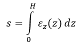
by summation using the “rectangular rule” with the division of the interval 0 ≤ z ≤ H into n parts that may be generally of different size. The values of σz,σor,m,Eoed with index i relate to the middle horizons of the strata. The accuracy of the summation can be increased through finer mesh, i.e. greater n.
Stress σz is calculated from surcharge loading σol in the foundation base that must be in practice analysed mainly by means of iteration, i.e. through the solution of a contact problem: building + foundation + subsoil. The load of the foundation would be transferred directly to the subsoil surface only in case of a very flexible foundation. The result functions representing the distribution of the contact stress across the foundation base are, in fact, generally statically indeterminate quantities. As already stated, they depend not only on the load, but also on the relative stiffness of the foundation with the superstructure in relation to the subsoil, on physical properties of the subsoil, on the time factor (changes during construction and service life, consolidation), etc. The foundation base is subjected to the load directly only in special situations (e.g. load from embankments) and if this happens, the surcharge loading is known in advance.
Stress σor is determined by the weight of the soil above the given point that is in the middle of the thickness of the stratum. The calculation requires that the values of the effective unit weight (i.e. above the groundwater level) are known and it is assumed that its distribution is constant in every stratum.
Considering formulas Equation 2.1 and Equation 2.2, it is clear that our standard defines for each stratum a rigid-elastic stress-strain diagram with singularity in point σz=σswhere the rigid model becomes elastic – see figure 2.2 below.
Figure 2.2: stress-strain diagram of soil according to ČSN 73 1001:
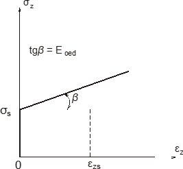
This strong physical nonlinearity results in the fact that the principles of linearity and superposition do not apply to the calculation of settlement and that it is not possible to use the same approach for the definition and assessment of the structure as in linear analysis. It would not be possible to evaluate separately individual load cases or use an automatic selection of the most effective combinations for each result quantity. Fortunately enough, the problem of the structure-soil interaction has certain specifics that allow for weakening of this strict limitation. Short-term variable loads involved in the load combinations do not produce (through their effects) settlement of the subsoil and, therefore, they do not have to be included into the complete loading for which the support parameters will be evaluated. The principle of the solution is that the long-term loads are concentrated into one of just a few load cases and the supporting conditions are calculated for this linear combination. During the evaluation we have to bear in mind that the results correspond only to the given total load and not to individual load cases. Concerning the short-term loads, these are included only into the formulas for the analysis of the most effective combinations. They may have an impact on the deformations and internal forces of the superstructure, but not on the calculation of the interaction parameters.
However, this approach is not recommended for problems in which the stress in the foundation base is influenced mainly by variable loads (e.g. light-weight steel halls) and the CS parameters must be calculated for each nonlinear combination separately.
Physical model of soil according to DIN 4019
Settlement is in the German standard calculated in the following way:
Equation 3.1:
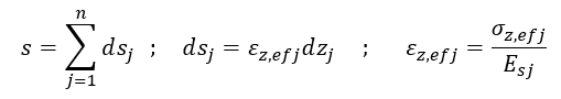
where:
dsj = compression of the j -th layer of the subsoil from the given surcharge loading
j = number of the layer with thickness dzj
n = total number of layers into which the deformed zone of the subsoil from the loaded place up to the limit height Hm is divided; geological strata represent a coarse division that is refined for mathematical reasons (numerical integration) similarly to formula of the Equation 2.1 for CSN
εz,efj = relative compression of the j -th layer from the given surcharge loading, it is the vertical component of deformation εzcalled in DIN 4019 “specific settlement” and marked s'z, which reminds derivational definition of εz= ds / dz.
σz,efj = vertical component of stress σz in the centroidal level of the j -th layer due to the given surcharge loading.
ef = index used to emphasise that we deal with the effect of the given surcharge loading, because DIN 4019 introduces stress-strain diagrams σz-εz valid for the complete stress- and deformation-state of the stratum including the initial geostatic stress-state and corresponding deformation.
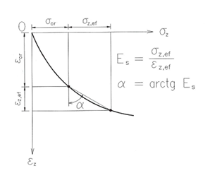
Esj = this is termed “average modulus of deformation” of the j -th layer that corresponds to the current stress-state and deformation of that layer. DIN 4019 defines it as a secant modulus of the graph σz-εzbetween two points: the original geostatic stress-state (σz,or,εz,or) and the stress-state after applying the surcharge loading (σz,or+σz,ef,εz,or+εz,ef) - see the figure 3.1 below.
Figure 3.1: DIN - secant modulus Es
Additionally, following issues might be mentioned:
a) The standard assumes that the stress-strain diagram σz-εz (figure 3.1) is provided for the calculation of settlement for every geological stratum starting from the initial state σ=0, εz=0 and ending with the state σz that is at least equal or greater than the expected state (σz,or,εz,or) . It is apparently a uniaxial constrained deformation as in CSN.
b) According to DIN 4019, the j -th layer first gets into the state of the original geostatic stress-state (which corresponds to σz,orfrom CSN standard) and this happens along the same path as given in the diagram (figure 3.1) i.e. by monotonous increase of σz. This defines the first point of the graph (σz,or,εz,or). Then, the surface is subjected to the surcharge loading due to the structure and both stress and deformation increase. The second point of the graph (σz,or+σz,ef,εz,or+εz,ef) is reached. What can be observed on the surface, i.e. settlement s, is just the effect of surcharge loading (σz,ef,εz,ef). That means that we are interested only in the secant modulus Es defined by the line connecting the two mentioned points of the graph. DIN draws stress σzalong horizontal axis and deformation εz(“specific variable settlement s'z") along the vertical axis downwards.
c) It is recommended to perform the summation (Equation 3.1) only within the limit depthHm defined by the requirement:
Equation 3.2:

which corresponds to the assumption that in depth Hm the coefficient m always equals 0.2 (m = 0.2 - see the coefficient of structural strength from CSN).
d) Stress σz due to the surcharge loading of the surfaceσ1 is in DIN 4019 mentioned only in the form of the following formula:
Equation 3.3:
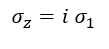
where "i" is the coefficient found in some table of results for a sequence. About 30 collections of tables by different authors are recommended and they limit only to a rectangular or circular surcharge loading area. A warning is given concerning various difficulties related to table-defined parameters. Therefore, it is more convenient to use directly the exact solution of the stress tensor for the elastic homogenous half space, as implemented in the CSN standard.
e) If the foundation is made in an excavation, the surcharge loading of the foundation base is reduced by the total original weight of the excavation σz,or,vand, consequently, only the following load is taken into account:
Equation 3.4:

This would correspond to CSN 73 1001 in a fictive situation with m = 1 for a stratum located at the foundation base in depth d, It means, that, most likely, only shallow excavations are considered.
f) Graphs required in points a), b) assume the possibility to perform an experiment with a specimen of the soil from each stratum. At the beginning of the experiment the specimen must be in the ideal initial state of released stress and deformation and the subsequent process must follow exactly the same path as in reality (in situ). Such an experiment is impossible in terms of time, even though the geostatic stress-state itself could arise trough monotonous increase of load, e.g. in sediments. It is clear that the graphs required in DIN 4019 must include professional experience and possibly adaptation for a given locality with its geological history taken into account. Therefore, DIN 4019 requires that the graph be produced by an established soil-mechanics laboratory.
Brief summary: The well known uncertainty following from the nature of geomechanical problems is in CSN 73 1001 implemented since 1988 mainly through the coefficient of structural strength m (0.1 ≤ m ≤ 0.5) and modulus Eoed. In DIN 4019, this uncertainty is included into the graphs (stress-strain diagrams of soils as virgin materials). However, the German design practice often avoids using these graphs directly in favour of their cumulative consequences, for example in the form of “average modulus Es in the analysed problem”.
Physical model of soil according to Eurocode 7
The EC 7 standard is rather tolerant and does not prescribe particular types of settlement calculation. It only recommends performing the calculation of stress using a homogenous half space and considering the value of the limit depth as defined by formula (Equation 3.2), the same way as stated in the DIN standard.
As the recommended magnitude of the limit depth is defined by the value equal to 0.2 of the initial geostatic stress-state, we suggest that the calculation of the compression of soil strata according to EC be performed using the CSN variant with the coefficient of structural strength equal to the same value, i.e. m = 0.2. The introduction of the limit depth means that the deformation modulus equal to infinity is assigned to deeper strata, which means zero compression. The strata just above should thus feature the minimum compression (in order to prevent the introduction of an unjustified singularity of the distribution of compression into the model), which is best suited just by the introduction of the term “structural strength”. This makes the formula for the determination of the limit depth logical and justified.
Concerning the excavations, we tend to support the idea that it is not suitable to deduct the weight of the excavation in determining the surcharge loading, i.e. we prefer to keep the value of the surcharge loading the same as if it acted on the original terrain.
Summary and example
The main difference in the estimation of the settlement is depicted in the Figure 5.1 below.
Figure 5.1: main difference between standards for soilin
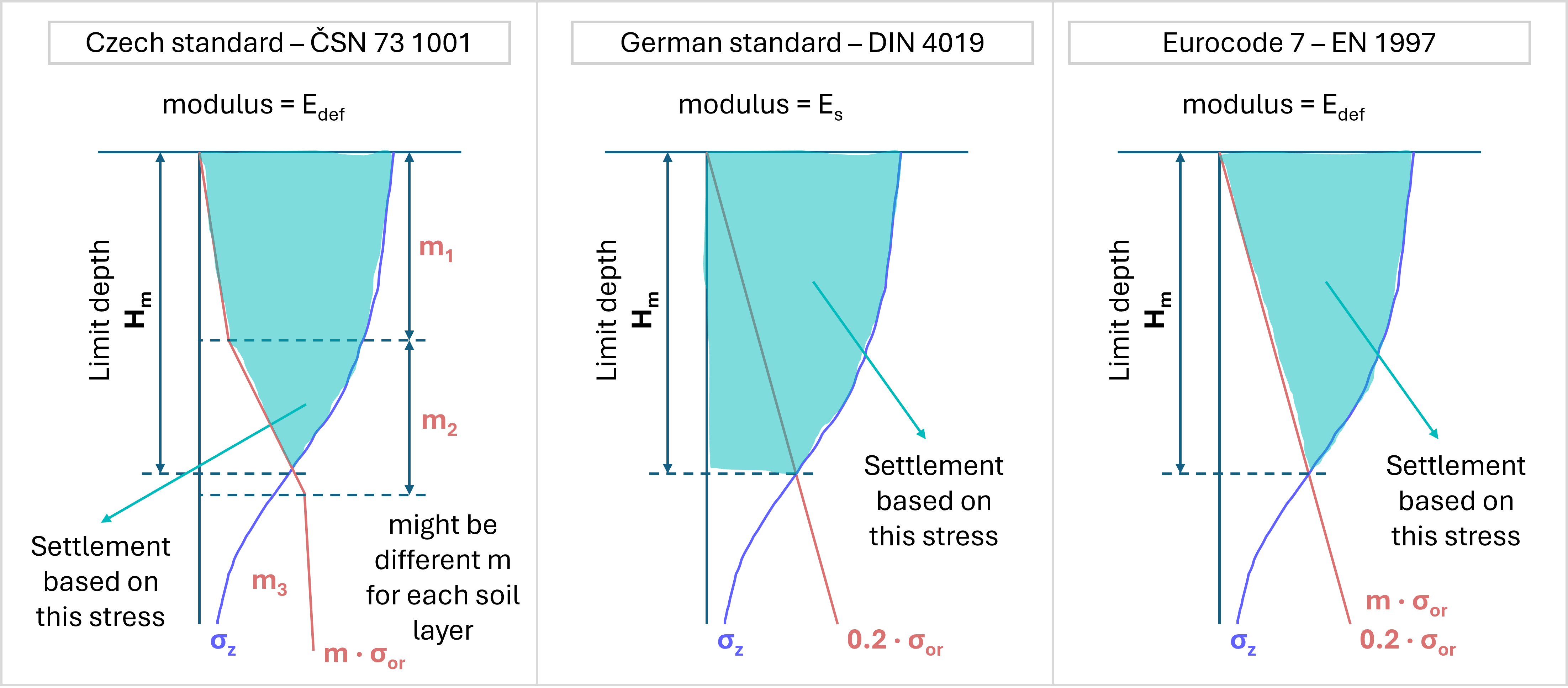
In the example below, there is a model of single slab supported by the soilin surface support. Layers of soil and material parameters are in accordance with the Figure 1.1.
Due to the fact there are different types of modulus to be defined for CSN (or EC) and DIN, there might be significant differences in the limit depth, and also settlement itself, if the same numerical values of moduli are kept (Figure 1.1) after change from the CSN "code for soil interaction" to DIN "code for soil interaction".
Note: the limit height in the example above is rather small, there was only little load applied.