Unit deformation of 1D member
This special unit load is available to be defined only within load case of "load type" = "influence lines", and "type of entity" = "Internal force" or "Deformation". See also Influence lines / surfaces work flow.
Icon of the special unit deformation load on 1D member:
The logic is explained in example below
Example - unit deformation of 1D member
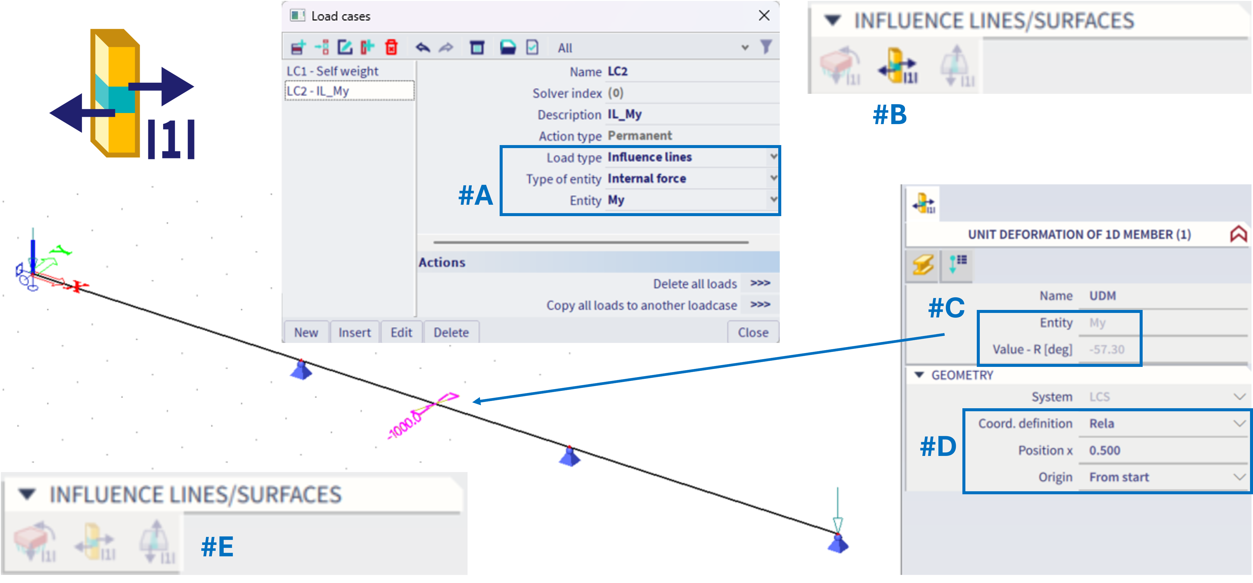
#A = The load case is set: Influence line, Internal force, My
#B = Within this load case (based on schema from this chapter), there will be automatically possible to define ONLY the corresponding type of load, and ONLY one of such load (by this, one exact position on the whole structure is defined)
#C = Within the load, the "entity" might be checked. This should correspond with the "entity" from the load case setting. The value is automatically considered as "one unit", e.g. in case of influence line for bending moment, the unit deformation is one radian (possibly depicted in degrees if set to within the unit settings) - this is only informative, not to be altered. In case of influence line for shear or normal force, there would be one meter considered.
#D = Properties to define the exact position of the special unit load on 1D member - hence, for what position the influence line should be considered.
#E = Once the unit load is defined, it is not possible to define additional one within the same load case, as ONLY one might be defined. If the unit load within this load case is deleted, it might be defined elsewhere on another beam.
Analogically this works for the influence lines of deformation, practically it is the same fro the user point of view - just to define exactly one position on 1D beam member for the corresponding special load case. The only difference is in the graphical depiction of this unit load, see figure below:
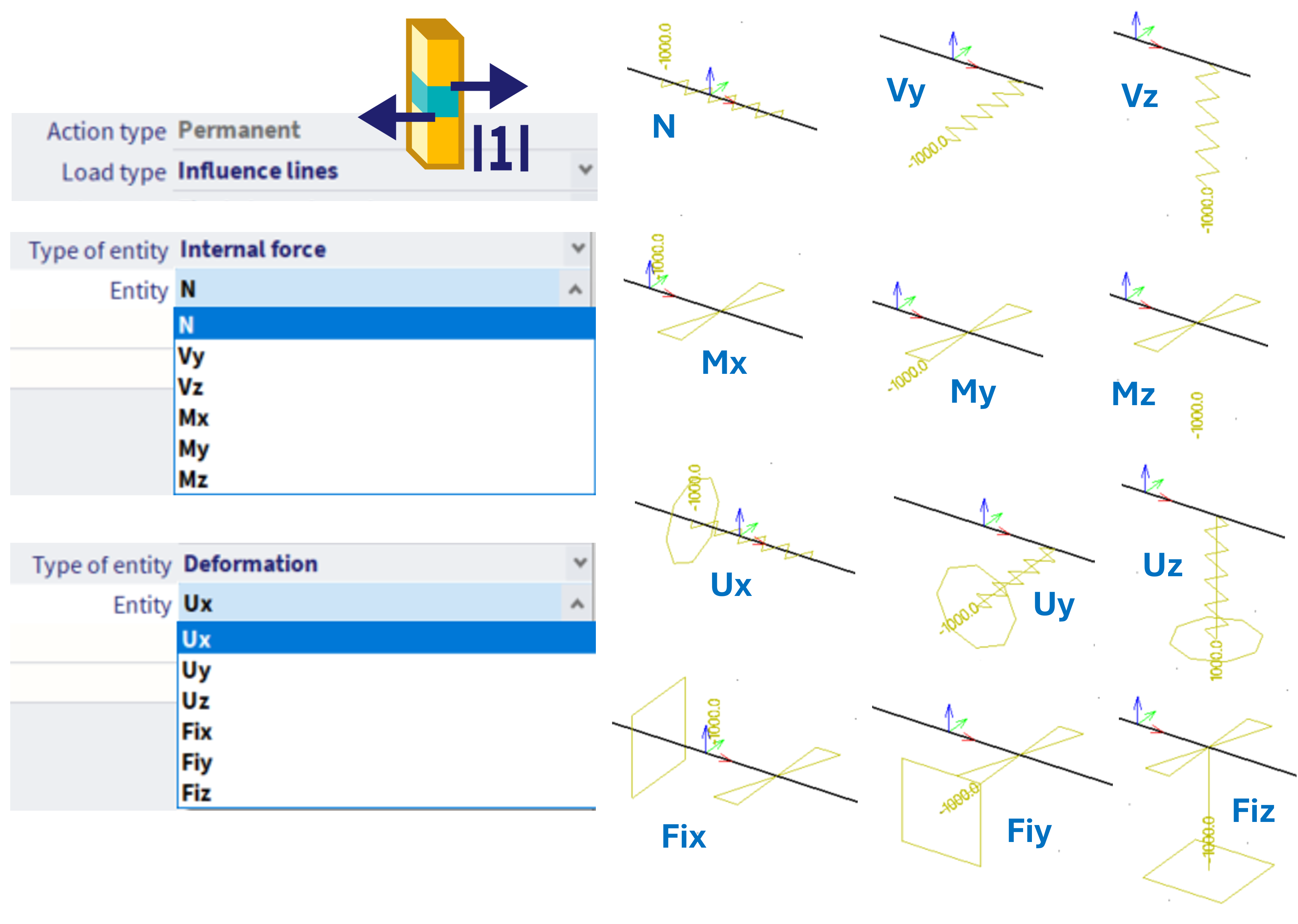
The symbols express the theoretical meaning of the unit load - e.g. in order to obtain influence line of force, the unit displacement needs to be applied in the corresponding direction (hence the symbol of this load is taken from classical "relative displacement on 1D" load), for moment influence lines, these are unit rotations. To obtain influence line of deformation, mathematically a corresponding constrain needs to be applied in the specific direction, along with the corresponding unit displacement (what is graphically expressed as the corresponding support plus the symbol of unit displacement or rotation in the corresponding direction). These symbols have only informative meaning, from practical point of view, the position of this load is critical.
Result of the special load case - the influence surface
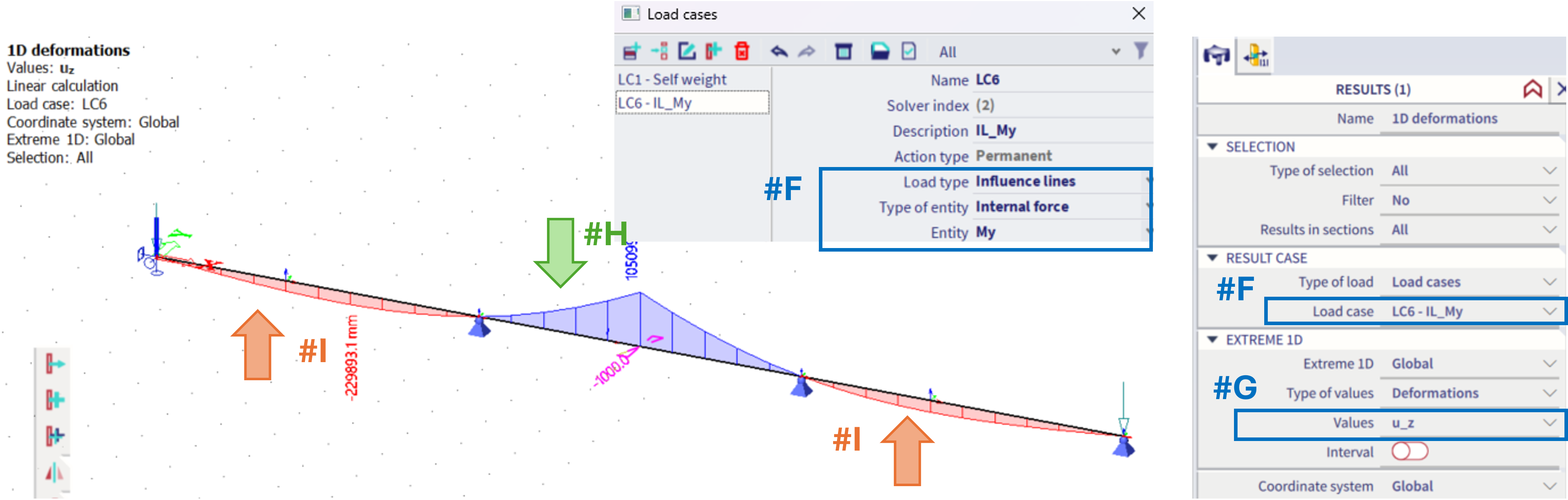
For the example of the My moment at the given position #F(In the second, middle beam of the structure), in order to see the influence line, the results of u_z (#G) of this corresponding load case need to be plotted.
In order to maximize the My, the load in opposite direction to the z-axis should be applied on positions with the positive result of he u_z (#H), and possibly load with the direction along z-axis applied in areas with the negative result of the u_z (#I). This result, the u_z value of the 1D deformations is the influence line for the considered 1D internal force (My) in the defined point on the structure (middle of the central beam).