Influence lines / surfaces - work flow
Influence line and influence surface - what it actually is
The influence line and Influence surface are actually results (deformation of the structure) of some specific load case. In general, the difference between the influence line and the Influence surface is only in fact, whether this result of deformation is deformation of a node which belongs to 1D beam member or 2D shell member. This result is in general anywhere on the whole structure, not just in area where the traffic lane is defined (where the moving load might be applied).
The specific load case (for which the results are considered as influence lines or influence surface) is ONE unit deformation of specific type, applied only in ONE position of the whole structure. In SCIA Engineer (since version 26), the influence line and influence surface are accessible by standard way of plotting displacements (1D, 2D, 3D, nodal displacements) on the structure. For practical purposes, user will be mostly interested in plotting these results on selected elements, e.g. those where the moving load will be directly applied. Nevertheless, displacements for whole the structure are always available.
If influence line (or surface) are to be calculated (standard linear static analysis), a special load case needs to be created for each influence line (surface), within the library of the load cases.
The load case needs to be set:
"Action type" = "permanent"
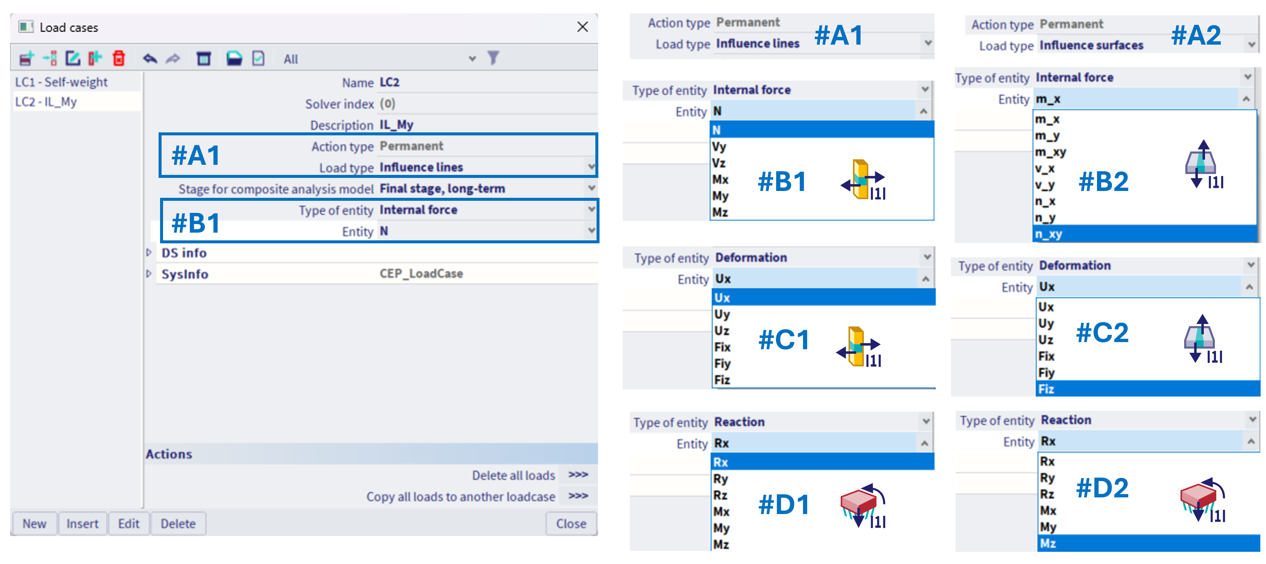
"Load type" = "Influence line" #A1, or "Influence surface" #A2. Here for practical purposes it is distinguished, even if it is theoretically the same (depends only on structure and the area where the displacement result is being checked). Nevertheless, if the 1D structure is to be analysed, "Influence line" needs to be selected, and if 2D structure, "Influence surface". In special case of structure mixed of 1D and 2D elements, e.g. some bridge structure, where the top of the bridge is modelled by 2D members, and there are 1D beam columns of this bridge, such "load type" needs to be selected, which corresponds with the extreme of the entity which is investigated; e.g. if the object of interest is normal force in some column (1D member), "influence line" needs to be selected, even when actually the moving load is applied on 2D members (top of the bridge), where the 2D results will be viewed as the influence surface.
Based on the selected "load type", the specific "Type of entity" along with corresponding "entities" are offered #B1 - #D1,#B2 - #D2.
These selected entities defines, which influence line is to be provided:
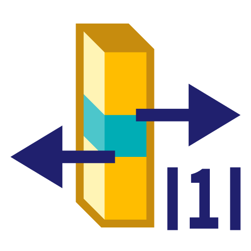
#B1- Influence line of specific 1D Internal force + which force
#C1- Influence line of specific Deformation (on 1D) + which deformation (in global coordinate system always)
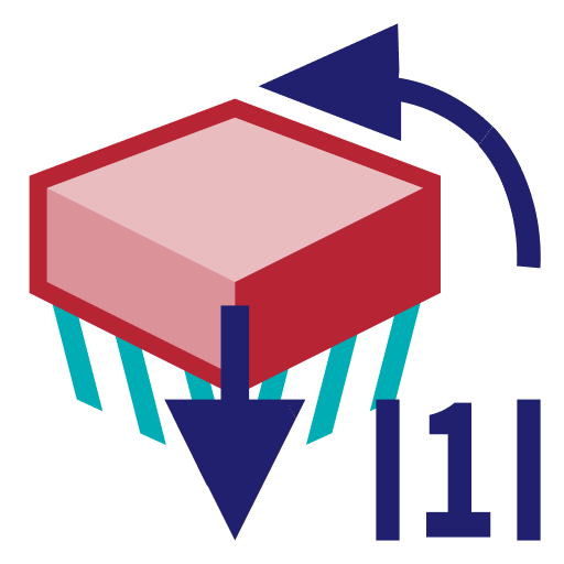
#D1- Influence line of specific Reaction (of some nodal support) + which reaction (in the coordinate system of the specific nodal support)
Analogically in case of influence surface:
#B2- Influence surface of specific 2D Internal force + which force
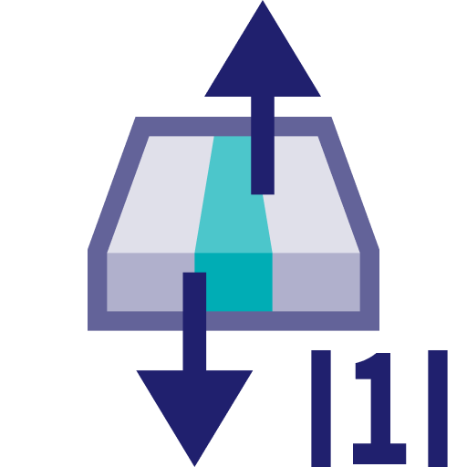
#C2- Influence surface of specific Deformation (on 2D) + which deformation (in global coordinate system always)
#D2- Influence surface of specific Reaction (of some nodal support) + which reaction (in the coordinate system of the specific nodal support)
For each of these special load cases (#B1 - #D1,#B2 - #D2), there will be only one corresponding type of this specific unit load possible to be defined within the load case, and only on one specific position. Hence, what kind of influence line to get is to be defined within this special load case setting, and where the extremes of the corresponding entity are to be evaluated, that is the content of this special load case itself (the position on structure defined by applying the special unit load).
According to the specific influence line (load case setting), the corresponding unit loads are available to be defined, see more detail in the corresponding chapters:
|
|
|
|
|
Either A) Unit deformation of 1D member |
The examples are provided for each of these three items in the corresponding chapters.