Unit deformation of 2D member
This special unit load is available to be defined only within load case of "load type" = "influence surfaces", and "type of entity" = "Internal force" or "Deformation". See also Influence lines / surfaces work flow.
Icon of the special unit deformation load on 2D member:
The logic is explained in example below
Example - unit deformation of 2D member
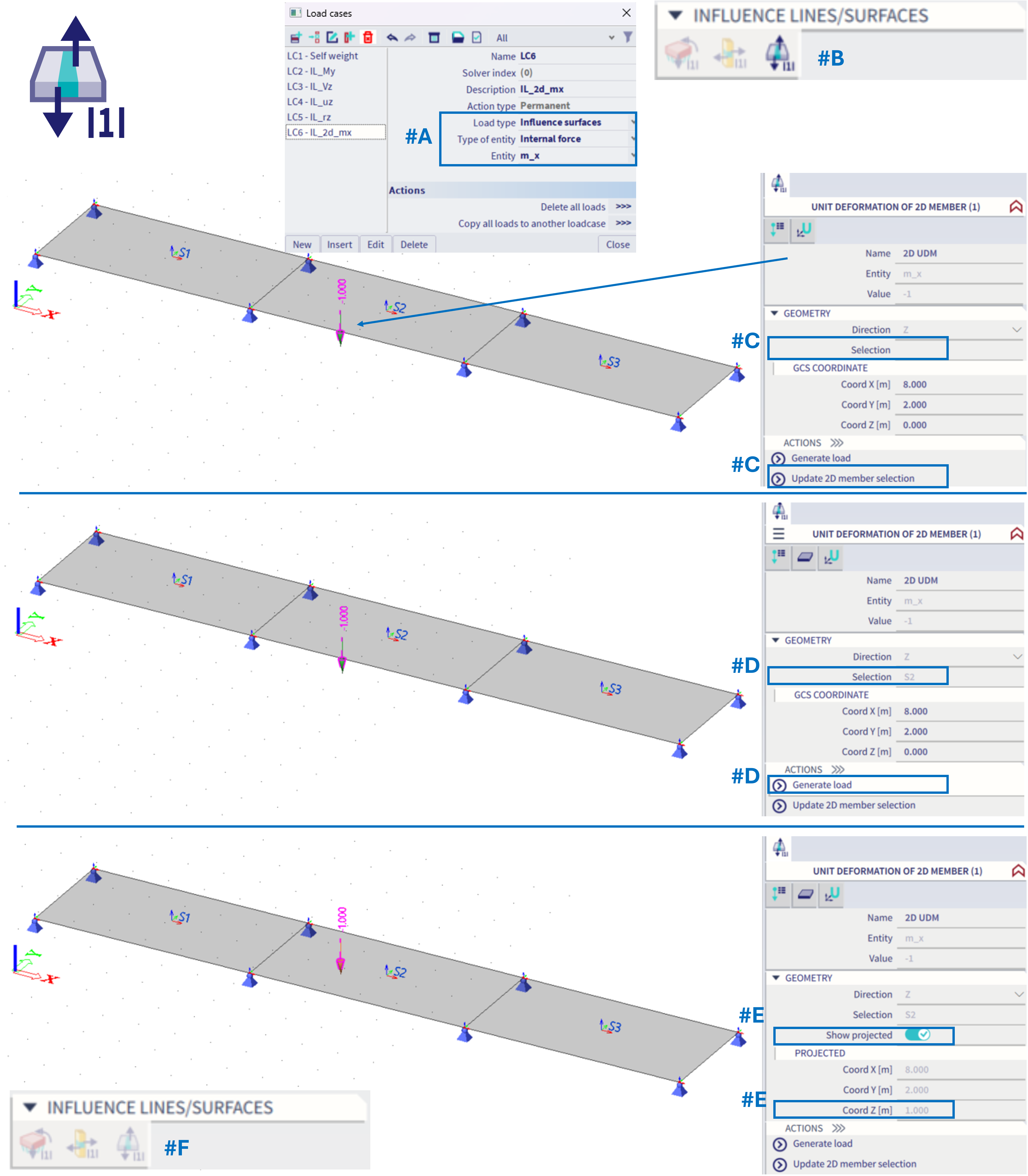
#A = The load case is set: Influence surface, Internal force, m_x
#B = Within this load case (based on schema from this chapter), there will be automatically possible to define ONLY the corresponding type of load, and ONLY one of such load (by this, one exact position on the whole structure is defined)
#C = In order to define exact position on 2D member, analogical feature to "free point load" is used. Firstly, within the active working plane, the position of the "unit force" needs to be defined. By default there is no preselected 2D member. One specific 2D member needs to be selected by the action button "Update 2D member selection". This selection allows to pick only one 2D member.
#D = Once the 2D member is selected (it appears within the property "Selection"), action button "generate load" should be used in order to project the input position of the unit deformation onto the selected 2D member. This projection is always done along z-axis of the global coordinate system.
#E = After the projection is done, check box "show projected" appears, which enables to see the projected position, and if deactivated, the original input position of the load. These two positions should differ in the z-coordinate of the global coordinate system GCS.
#F = Once the unit load is defined (not necessarily projected), it is not possible to define additional one within the same load case, as ONLY one might be defined. If the unit load within this load case is deleted, it might be defined elsewhere in space and projected on a different 2D member.
Analogically this works for the influence surfaces of deformation, practically it is the same from the user point of view - to define exactly one position on 2D member for the corresponding special type of the load case.
The symbol of this load is always an arrow pointing in z-axis GCS direction, the projected load is plotted by an orange arrow, the original input one by green. In case the projection from the defined input point onto the selected 2D member (along GCS z-axis) does not exist, the arrow will be plotted by grey colour. This behaviour is analogical to "free point load".
In basic, this special type of load is to define one exact position on one selected 2D member, which is done by the input point and projection (in order to easily define specific point inside the 2D member area)
Result of the special load case - the influence surface
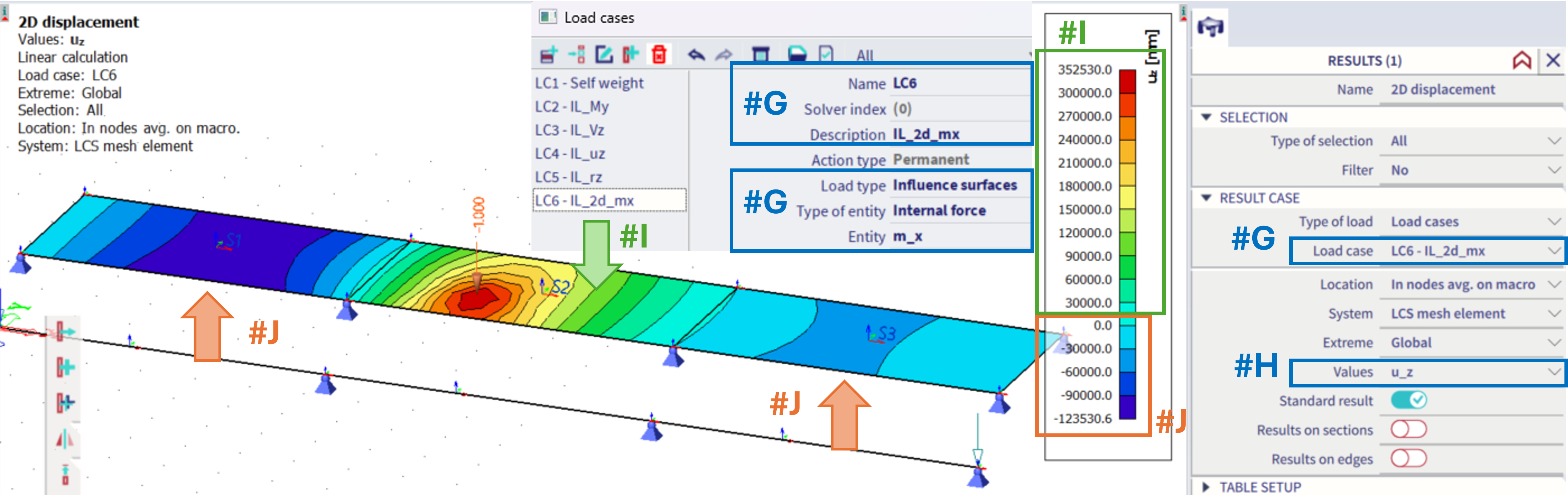
For the example of the m_x moment at the given position #G(In the second, middle slab of the structure), in order to see the influence surface, the results of u_z (#H) of this corresponding load case need to be plotted.
In order to maximize the m_x, the load in opposite direction to the z-axis should be applied on positions with the positive result of he u_z (#I), and possibly load with the direction along z-axis applied in areas with the negative result of the u_z (#J). This result, the u_z value of the 2D displacement is the influence surface for the considered 2D internal force (m_x) in the defined point on the structure.