Moving loads 1D - practical examples
This chapter provides few practical examples how to model Traffic lane 1D, define the Load Systems 1D and set the corresponding configuration in the Moving loads generator 1D.
1) Simple crane
Lets assume a simple hall structure with a crane, that would load two sets of parallel beams - see the figure below.
Steps:
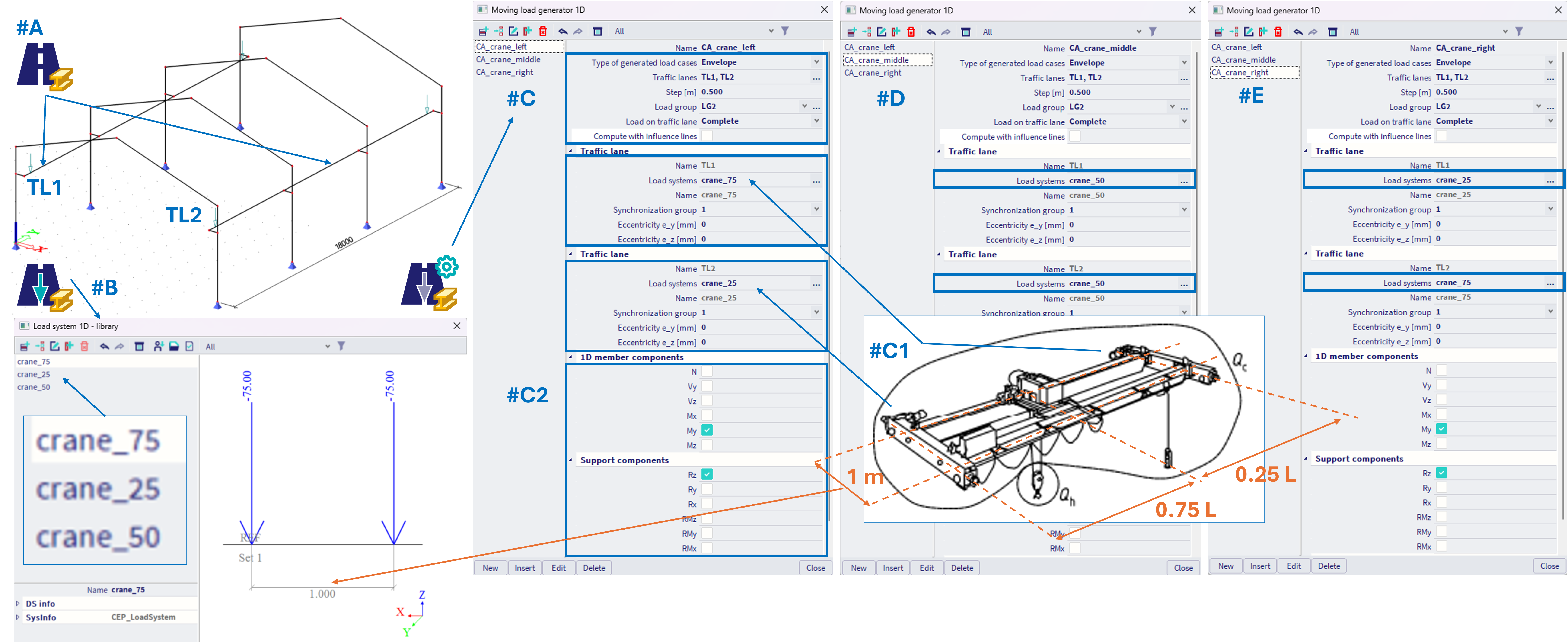
#A - Define two separate traffic lanes (in example named TL1 and TL2) by Traffic lane 1D. TL1 consist of beams positioned to the right, and TL2 consist of beams positioned to the left of the hall structure.
#B - Define the corresponding load systems within the Load Systems 1D library. In the simple example below, there are 3 load systems named: crane_75, crane_50 and crane_25, each consist of two concentrated forces spanning 1 m, where 75, 50 and 25 are values of the forces in these load systems in kN respectively.
#C - In the Moving loads generator 1D, lets assume we are interested in three positions of the "hook load" Qh (see also #C1), within the crane. This example oversimplifies the case, considering the hook load is much larger than the crane load Qc, which would be rather evenly distributed, Qh >> Qc, so Qc effects are neglected. In order to model this, three separate combination assemblies (CA) needs to be created, named: CA_crane_left (#C), CA_crane_middle (#D) and CA_crane_right (#E). In each of these CA, both TL1 and TL2 are being used, as the crane imposes a load on both traffic lanes.
For example for the case CA_crane_left (#C), the load system crane_75 is assigned to the TL1 and crane_25 to TL2, hence the TL1 is loaded more intensively. It is also important to assign each "load system - traffic lane - pair" into the same synchronization group (no matter what number, but needs to be same), in order to consider the fact, that these load systems are moving "together" along their traffic lanes. Analogically in the two other CA, the corresponding load systems are assigned to traffic lanes accordingly (see #D, #E).
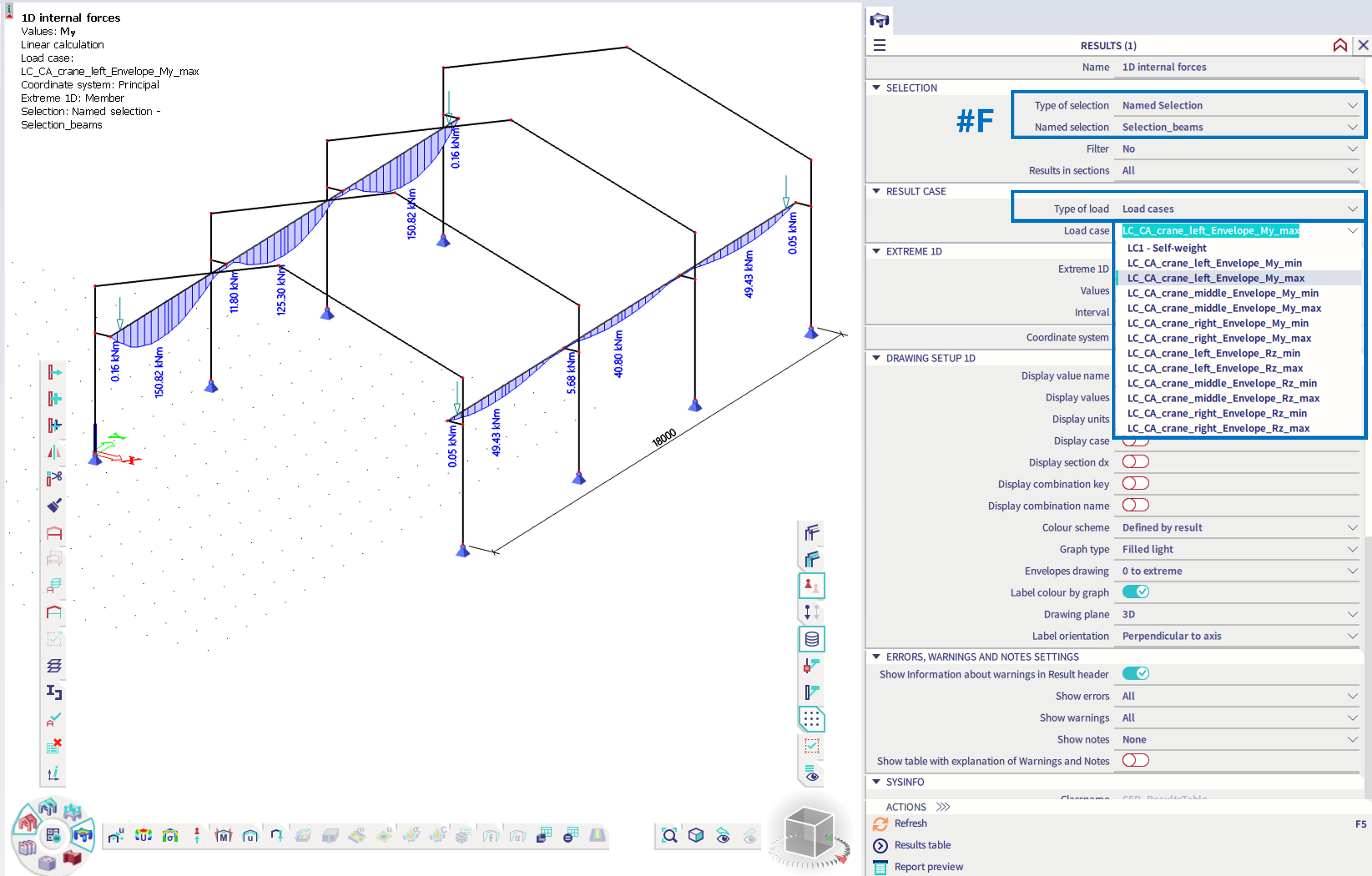
User needs to select, in which internal forces or reactions he will be interested (#C2). Based on this selection, the corresponding result load cases will be generated (#F), which might be further used within combination with the other loads (self weight, other permanent loads, climatic loads, etc.). The appropriate load group (#C) needs to be defined for each CA, which is set to "exclusive", in example named LG2.
After the analysis, it is possible to check the internal forces of the generated result load cases - in the example below, only results for the selected beams are provided (#F).
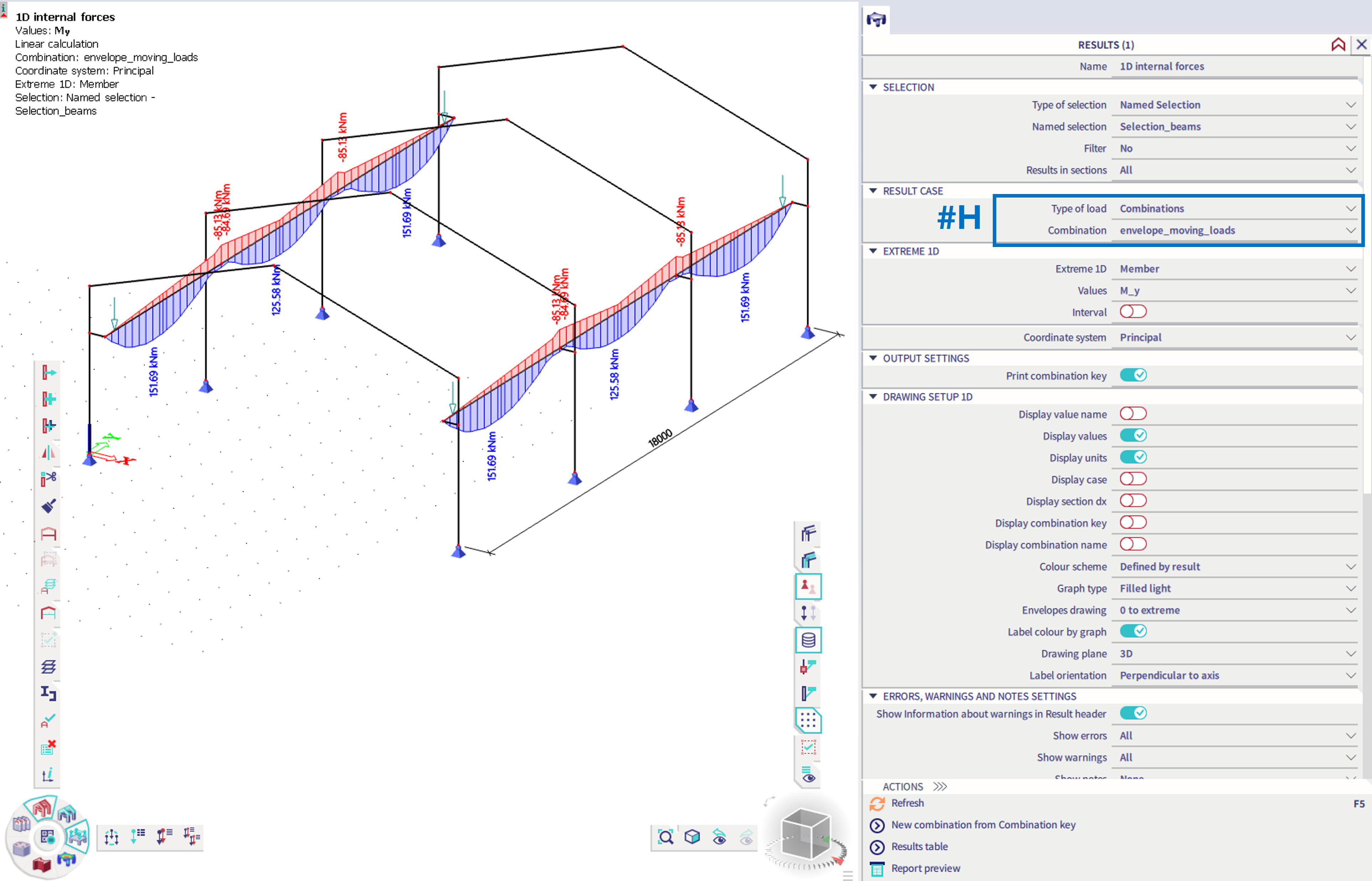
In case for further processing of these results, a linear envelope combination of these result load cases needs to be done either manually (#G) or also automatically generated Eurocode combinations might be considered.
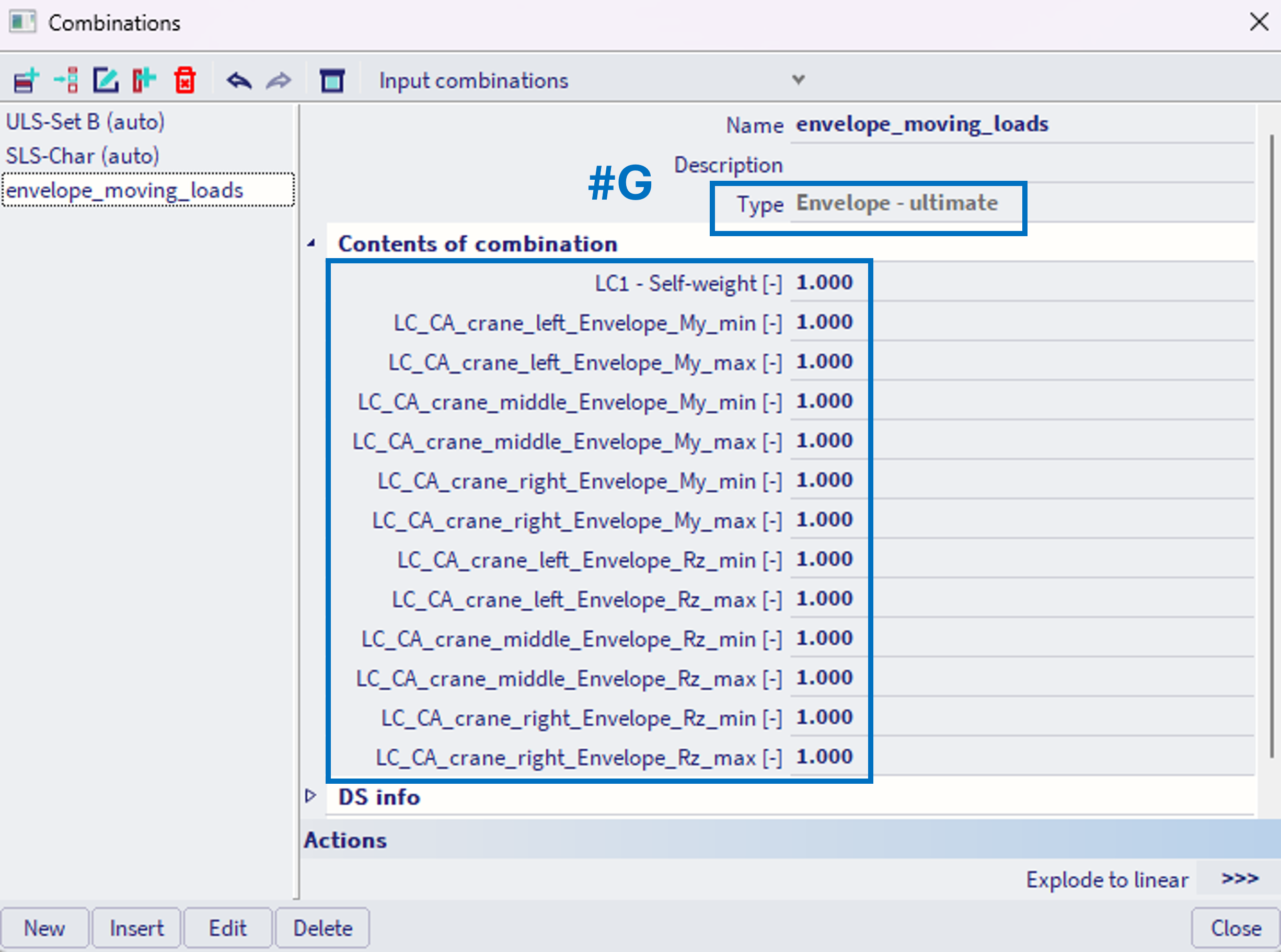
The results of such combination might be checked (#H) and further used for the design checks of the corresponding components (#C2).
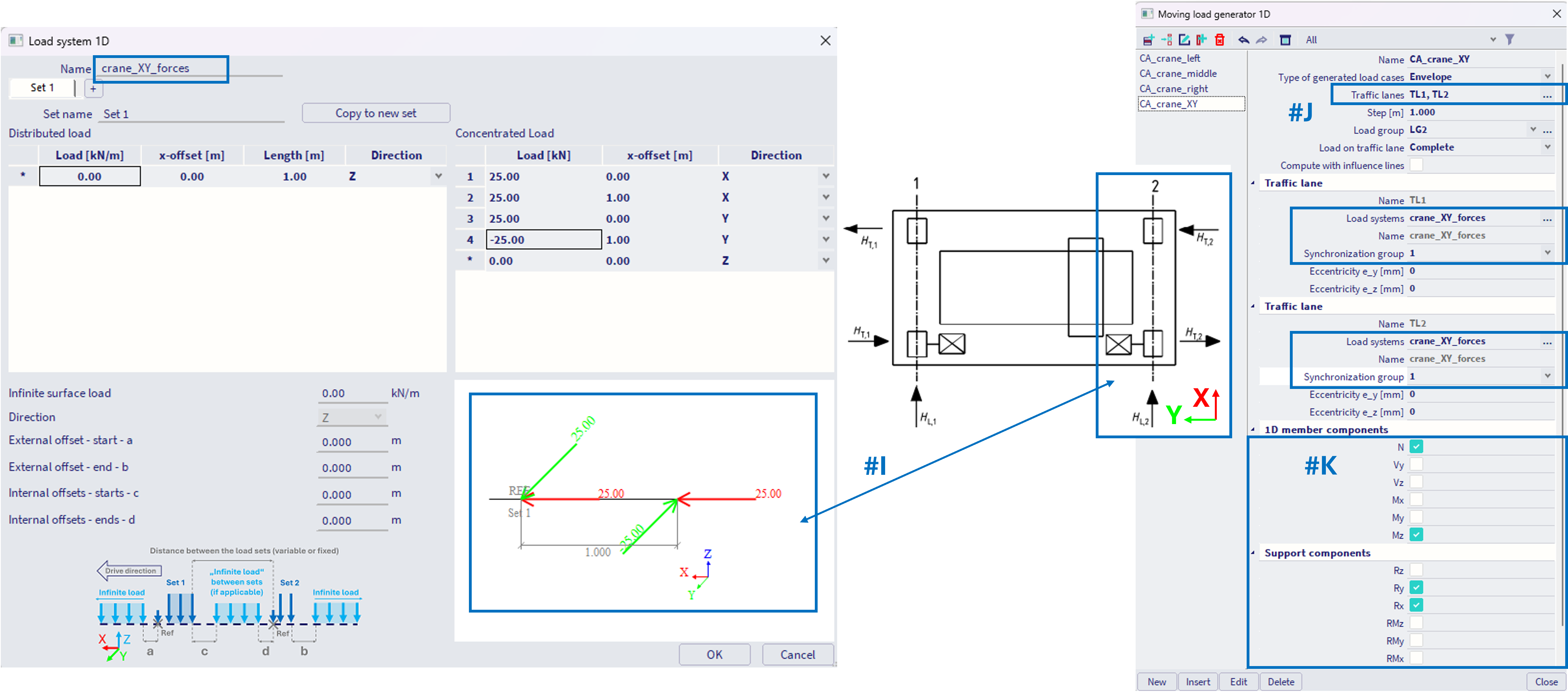
It is also possible to define loads in different directions imposed by the crane within the load system (#I), e.g. horizontal loads along X and Y axes. The simple example below assumes HT,1 = HT,2, so only one load system is used for both traffic lanes TL1 and TL2 (#J). Again, the corresponding components needs to be selected (#K), which are later objectives of design checks. If these forces HT,1, HT,2 are different, unique load system needs to be assigned to each traffic lane within the corresponding CA.
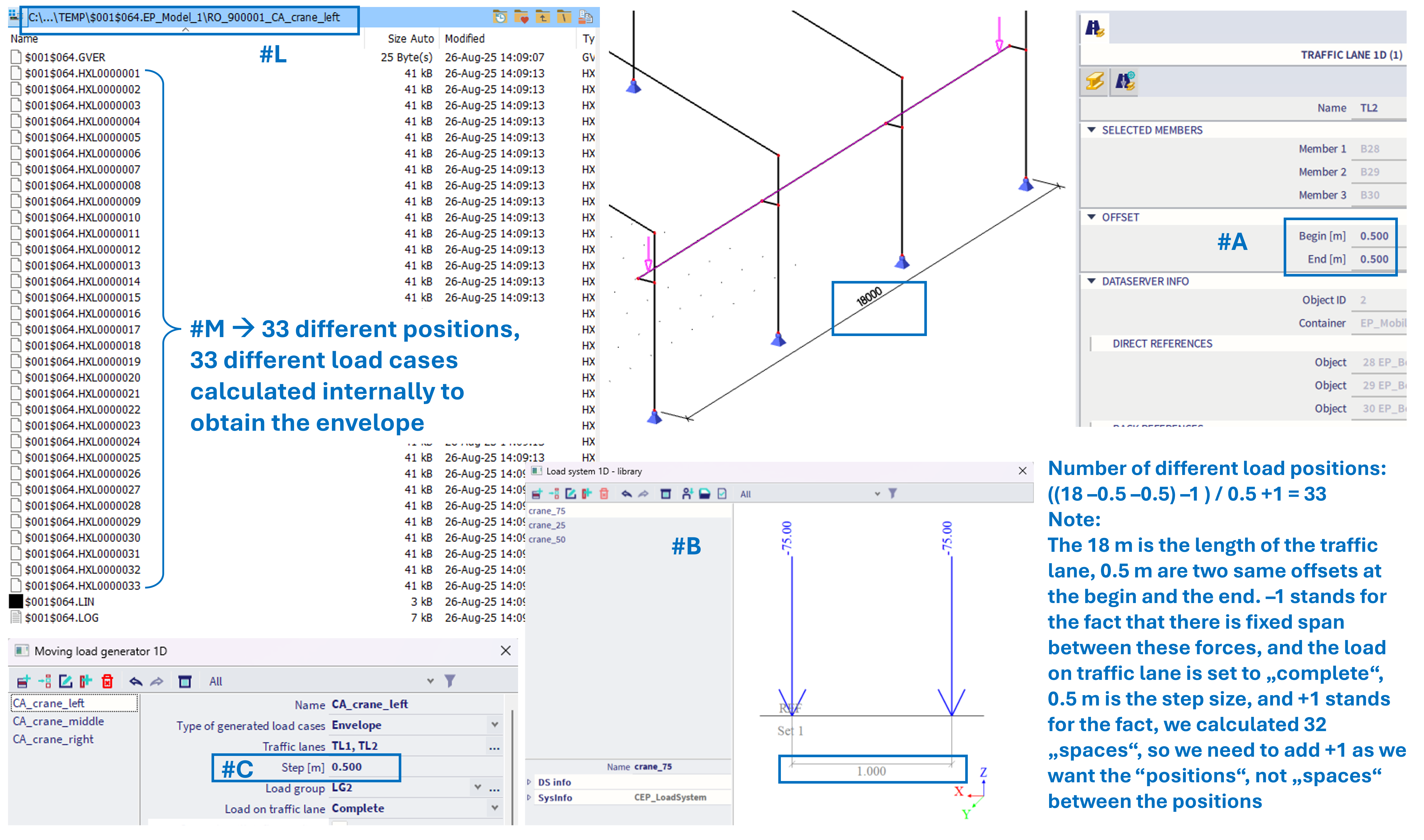
Note: user can "verify" the number of different load positions which is internally considered in order to get the envelope of the CA entity. Each CA internally generates several linear load cases. For the example of the CA_crane_left from above (#A, #B, #C), 33 different load positions are expected (calculation see in the figure below; note this calculation is valid only for this specific example, it depends on specific settings). After analysis, user can check the TEMP folder, and the sub folder of the corresponding CA entity. There should be 33 result files *.HXL0000001 - *.HXL00000033, each with results of one specific position of the load. It is not possible currently to check these specific positions graphically though.
2) Three lane bridge
In this example, a simple two-span beam bridge is considered.
One Traffic lane 1D , TL1 is defined. There are no offsets at the begin neither end of the traffic lane -#A.
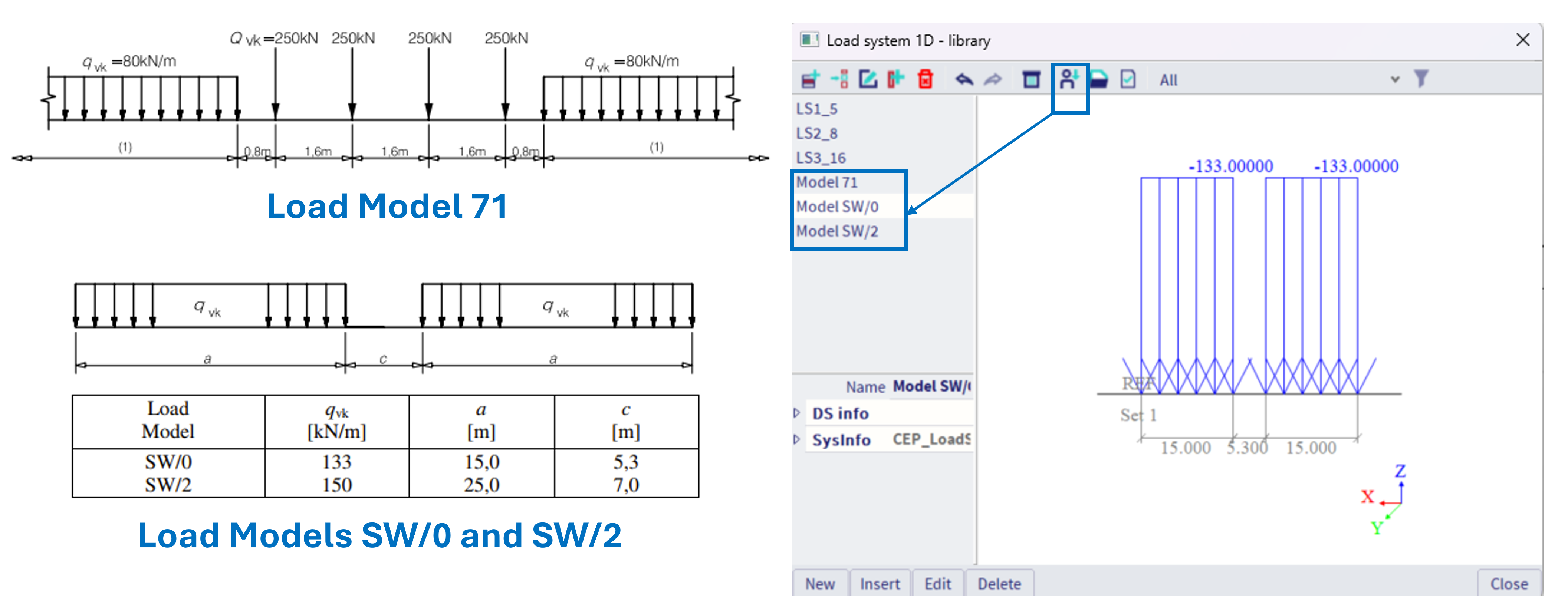
Three different Load Systems 1D are defined (#B). These load systems are quite similar, differs in the load intensity.
Each load system has defined two sets (#C). In the first set, the "infinite load" is defined at 0.5 kN/m (more detail see part #G in Load Systems 1D). The distance of the second load set is set to "variable", with minimal distance of 1 m, maximal of 2 m, and step of 1 m.
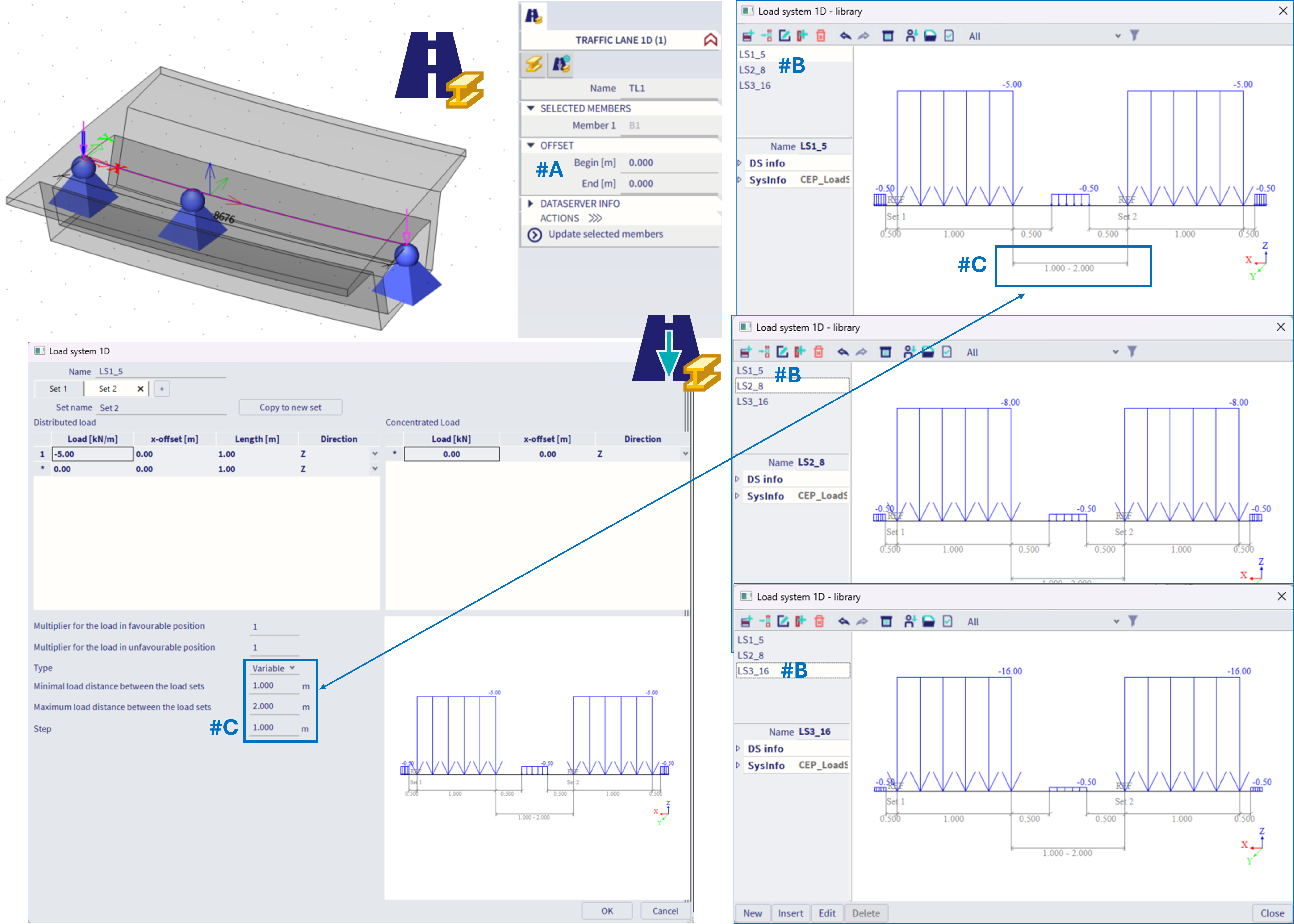
This means, such load system contains two various positions between its load sets, as depicted in the figure below, position with 1 m distance between the end of the set 1 and begin of the set 2, and 2 m distance:
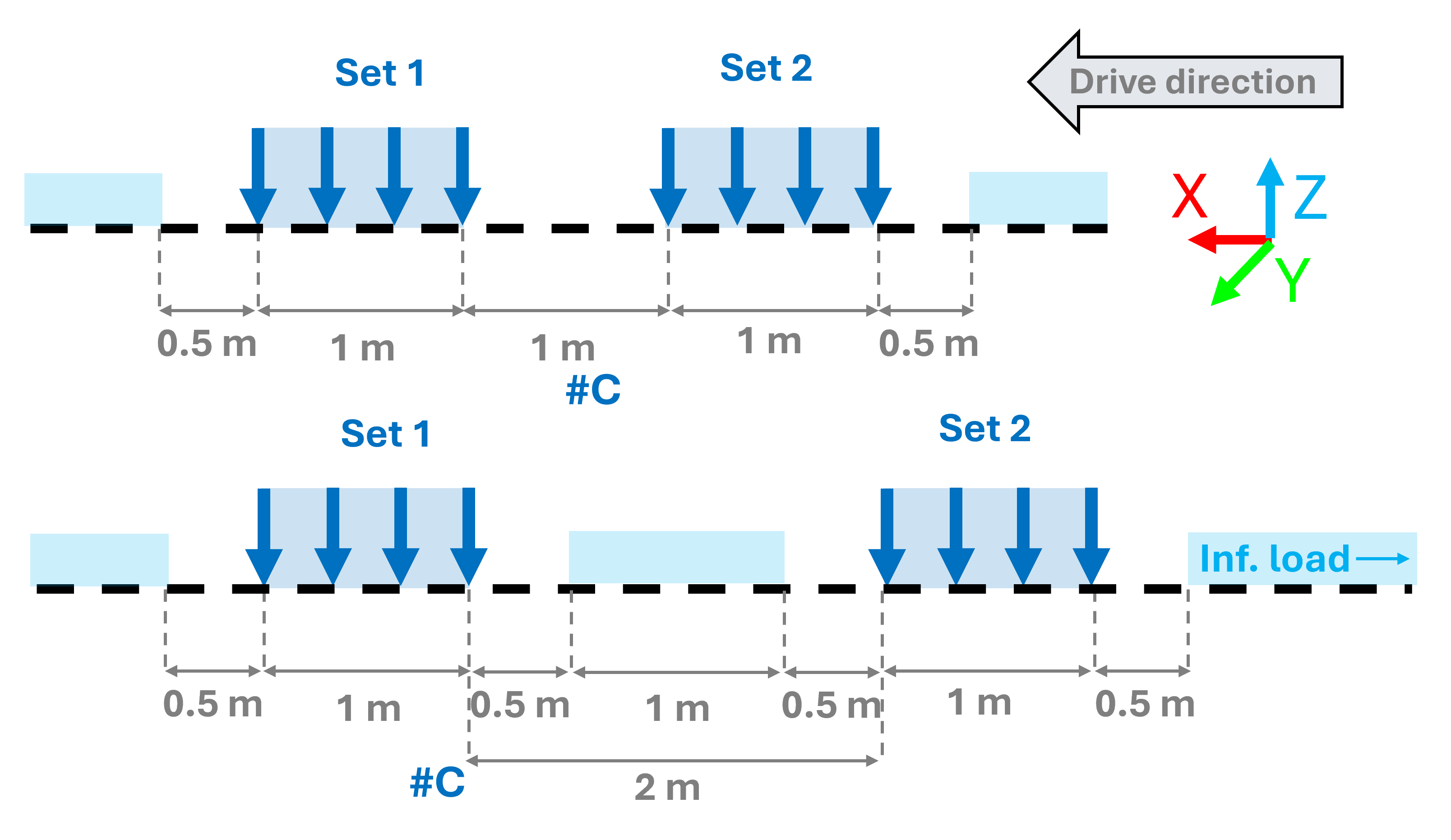
All these sets are combined together within the Moving loads generator 1D, along with the traffic lane (#A). The "load on traffic lane = partial" means, also such positions of load systems will be considered internally, where at least some loads of the load system are positioned at the traffic lane. This simulates loads of the traffic, in the moment of entering and leaving the analysed bridge structure.
The Step of 1m within the Moving loads generator 1D, stands for the step size, which is considered for the various positions of the whole load system on the traffic lane. In case there are several traffic lanes on the bridge itself (real structure lanes, in this example 3), this is handled by the corresponding assignment of the load systems to one Traffic lane 1D, where the load systems are defined with appropriate eccentricities (#D). Each "load system - traffic lane 1D" might be also assigned to a specific "synchronization group". In this case, load systems LS1_5 and LS2_8 are in the same synchronization groups, hence the loads in these load systems (lanes) moves "together" - there are no mutual variations of the different positions. The third LS3_16 is not synchronized with any other group, this means loads in this lane ("load system - traffic lane 1D") move independently on the remaining bridge traffic. There are practically 2 groups, making the number of various load positions ^2 (power 2). In case all these 3 load systems will be in separate group (equivalent with synchronization group = "none"), there would be much more mutual variants, more precisely ^3 (to the power of 3).
Note: too many unique synchronization groups, combined with fine steps within the Moving loads generator 1D, and Load Systems 1D would lead to numerous variations of the load positions, making the analysis impossible. In such case a warning will be encountered. It is also recommended, in order to speed up the result reading of these numerous background cases, to define exceptions for all the SCIA Engineer related files, folders, etc. into the antivirus software (or windows defender) installed on the corresponding computer.
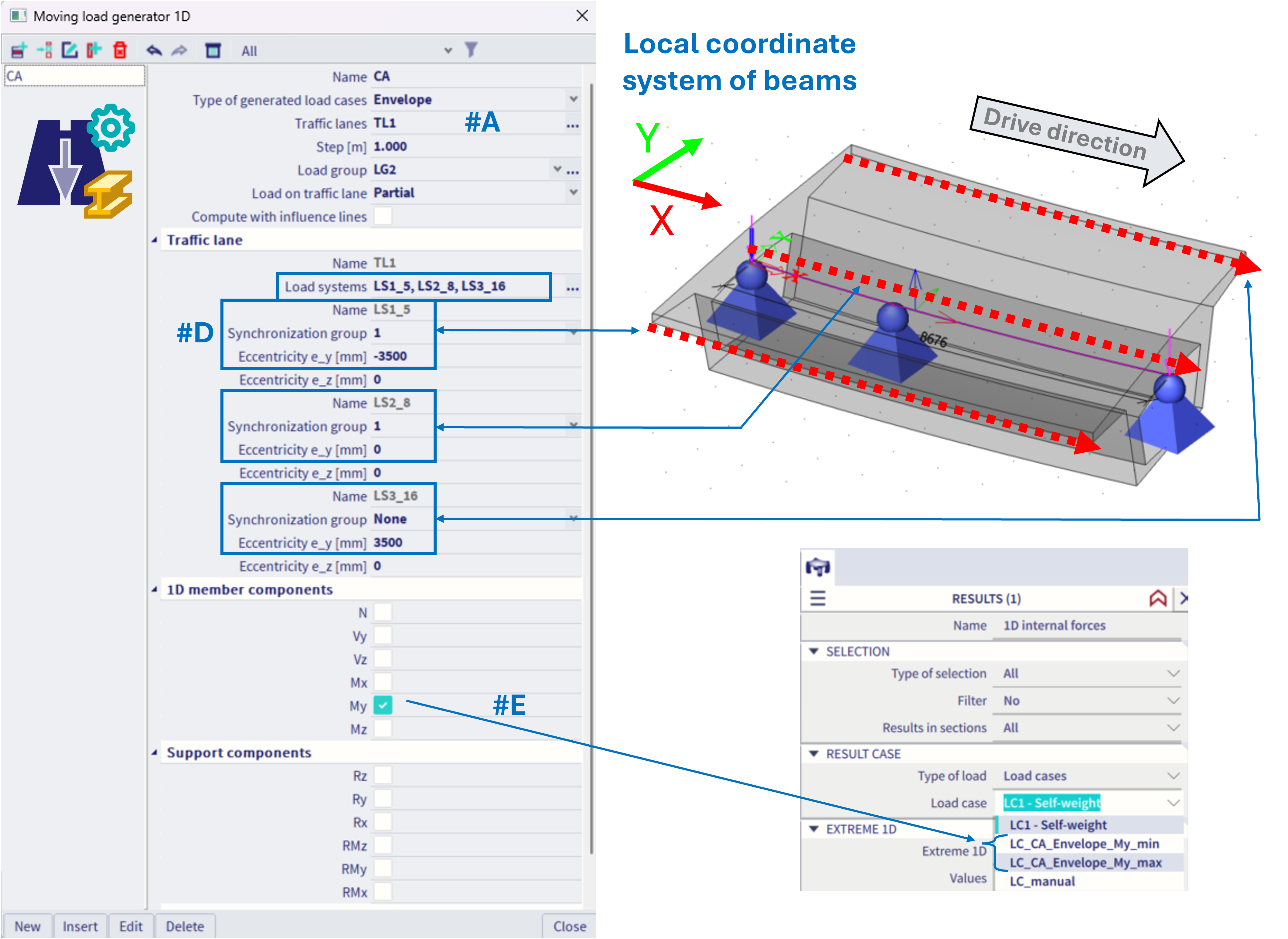
The selected member components (#E) work the same way as in the previous example of the crane structure.
3) Using system database library
Load systems 1D from system database library might be also used, see figure below