Load Systems 1D
Applicable to load 1D members.
Icon of the command:

Defining of the Load system 1D
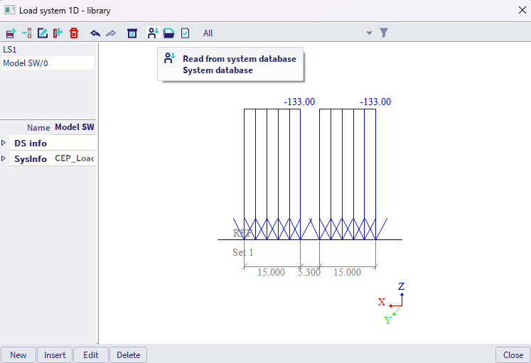
In the library of the load system 1D, user can select load system either from predefined database, or create a new unique load system.
Creating new unique load system
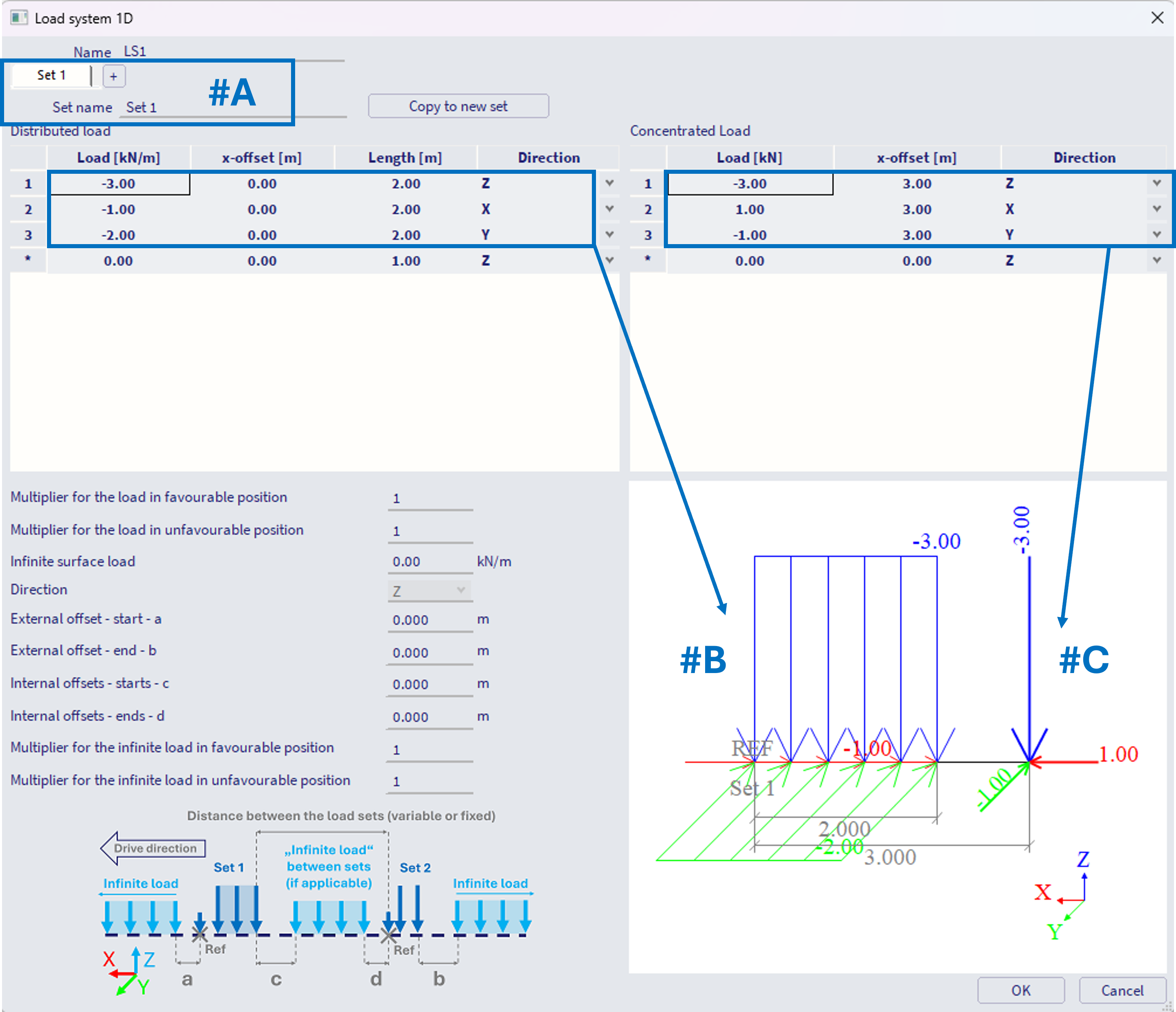
#A -Load system might be divided into several Sets. Imagine these Sets as cars, trucks or carriages, where the distance between each set might (or does not have to) alter during the traffic.
#B -For each set, distributed load might be defined by the load value, load direction, offset (distance "backwards" from the reference point of the set), and length where the distributed load is acting.
#C - Analogically, concentrated load might be defined.
Both types of loads are being graphically depicted in the axonometric view in the bottom right part of the Load system dialogue.
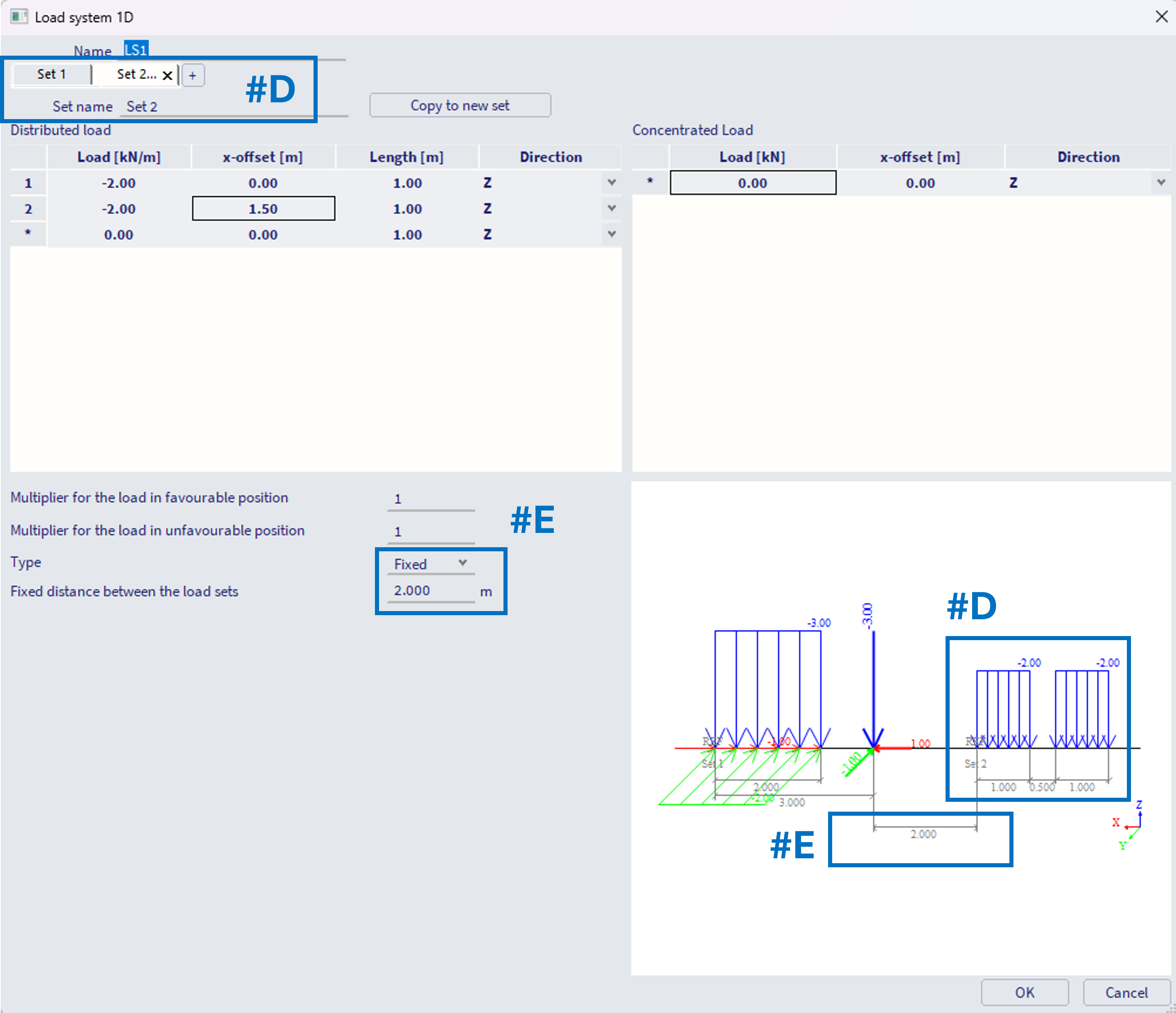
#D - Subsequent sets are created by "+" symbol in the bar, or by copying the existing set. Loads are defined the same way (steps #B, #C)
#E - For each subsequent set (after the first set) it is necessary to define the distance from the previous set. This distance is considered from the reference point (the begin) of the current set to the position of the last load of the previous set (on example below 2 m from the concentrated force of the set 1 to the reference point of the set 2). This distance might be defined as fixed, constant (e.g. carriages of a train not altering the mutual distance between each other).
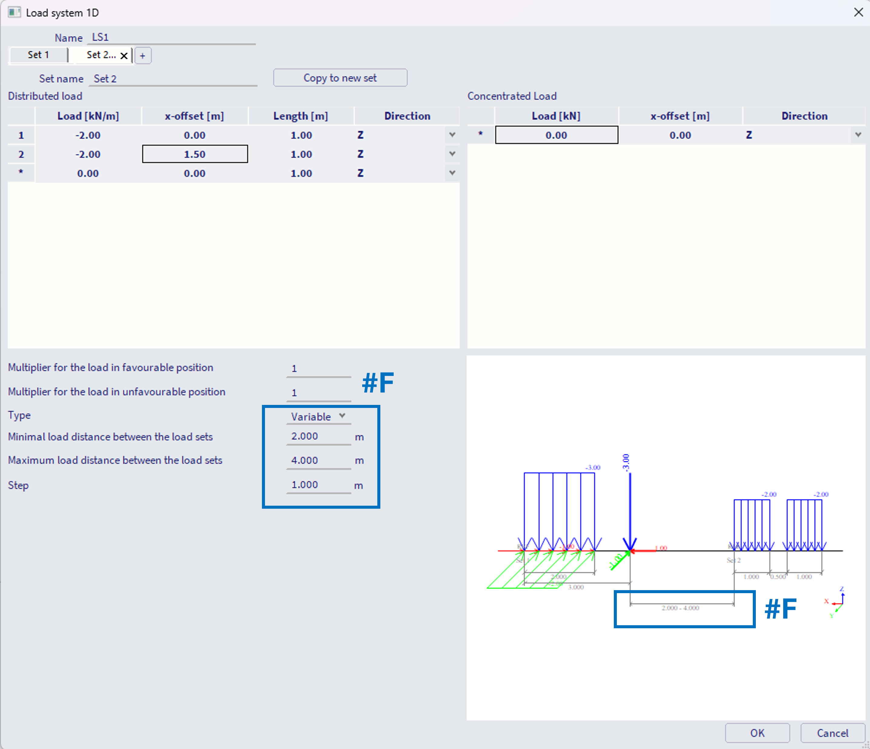
#F - Alternatively, this distance might be set as variable, with defined minimal and maximal distance between the subsequent sets, and the (maximal) step size. In example below, the minimum is 2 m, maximum 4 m with step of 1 m, what means internally three positions will be considered, distances of 2, 3 and 4 m between these sets.
Note: if the difference between the user input max and min is not divisible by the user input step without remainder, the value "(max - min) / step" is rounded up to whole number, and step size is internally considered a bit smaller, hence the step size is considered as "maximal".
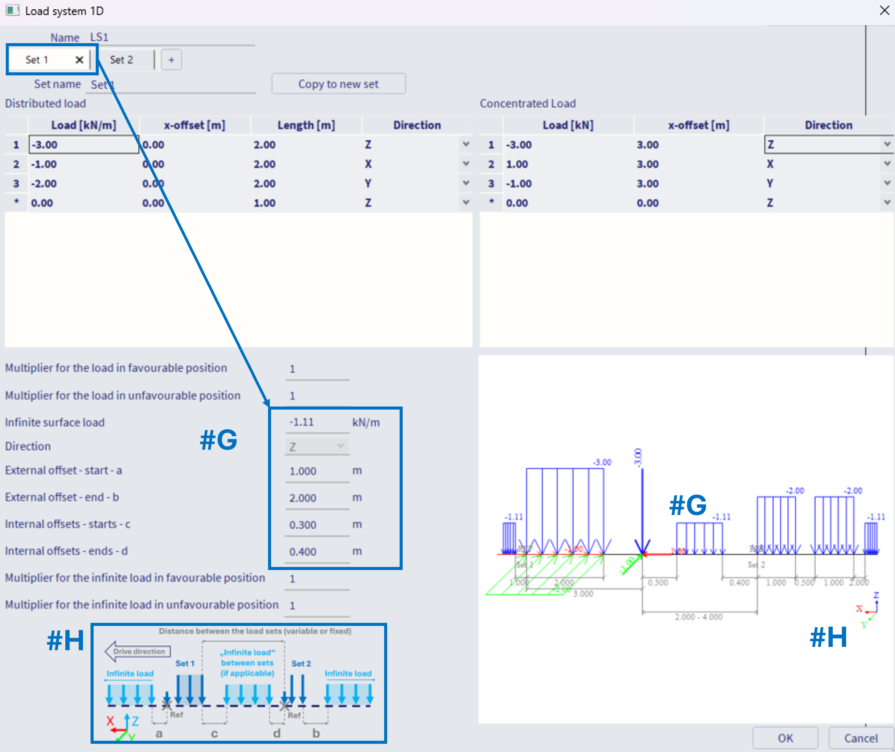
#G - It is also possible to define so called "infinite line load", which is being applied between the sets, before the first set, and after the last set of the load system. This infinite load to be defined within the first set of the load system. It is considered (and graphically plotted in the axonometric view) if its value is different from 0. External and internal offsets (parameters a - d) might be defined to define spacing between this infinite load and the sets of the load system,
#H - Note the informative figure to help You define the loads. The drive direction of the system is defined in a way that the "set 1" is the first vehicle of the system, and any defined "x-offset" (#B, #C) is considered "backwards", in the opposite direction to the drive direction.
Load multipliers within the Load system 1D
There are two types of multipliers for the load to be defined within sets of load system. All these multipliers are ONLY considered if the load system is used within the CA entity of the Moving loads generator 1D, which is set: "Type of generated load cases = Envelope" AND the check box "Compute with Influence lines" is activated. It is being ignored in case load system is used within CA entity of the "Type of generated load cases = Envelope", where the check box "Compute with Influence lines" is off.
Alternatively, these multipliers are also considered within the CA entity of the Moving loads generator 1D, which is set: "Type of generated load cases = Influence Lines
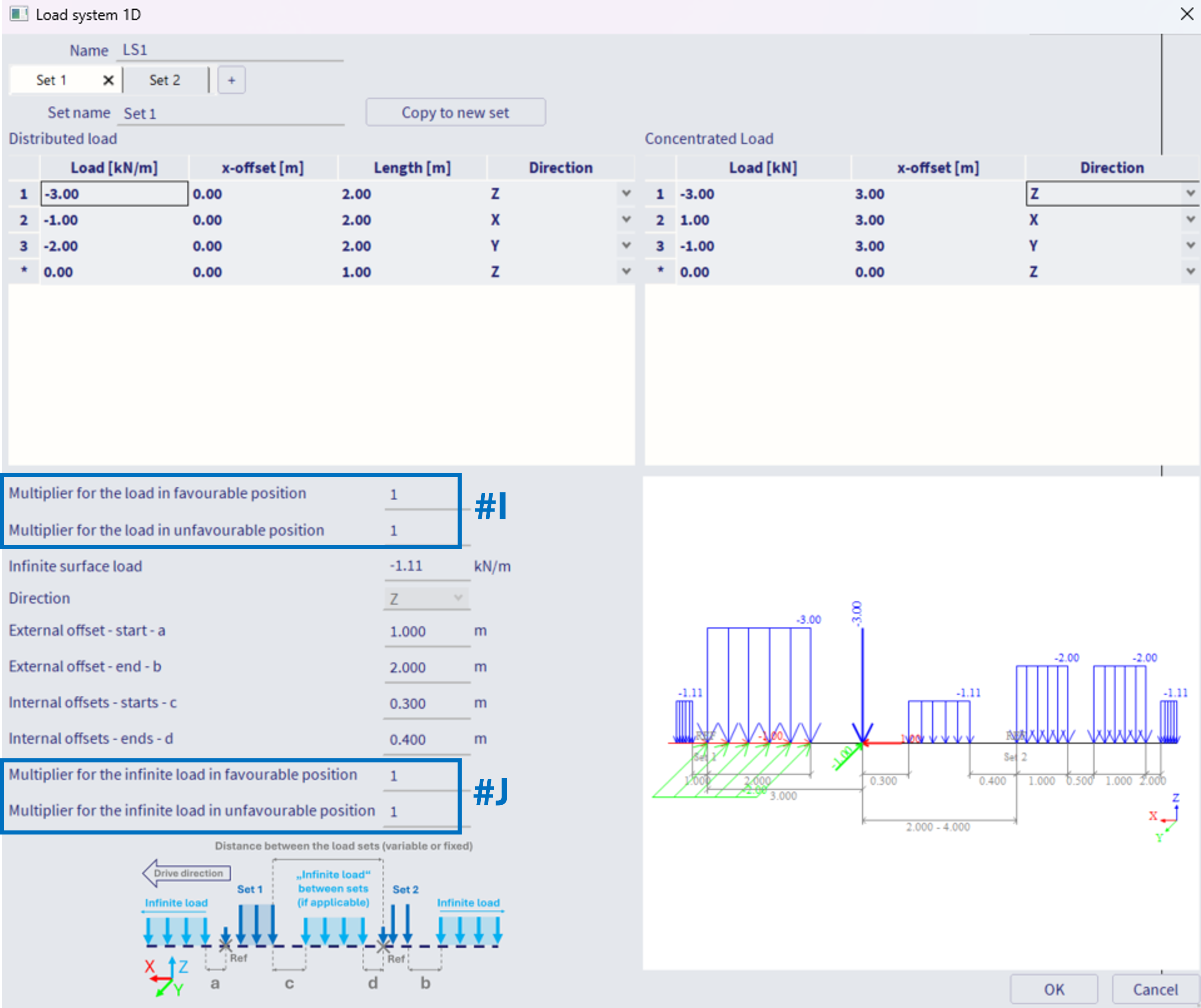
#I - Multipliers for the load:
Multiplier for the load in favourable position
Multiplier for the load in unfavourable position
These multipliers are used to multiply the load from the corresponding set, in accordance whether its current position contributes to increase or decrease of specific component (internal force) in considered position. Note: hence only usable with the influence lines option, where internally the influence lines are being calculated.
#J - Multipliers for the infinite load:
Multiplier for the infinite load in favourable position
Multiplier for the infinite load in unfavourable position
These multipliers works analogically to #I, just applied for the infinite load.
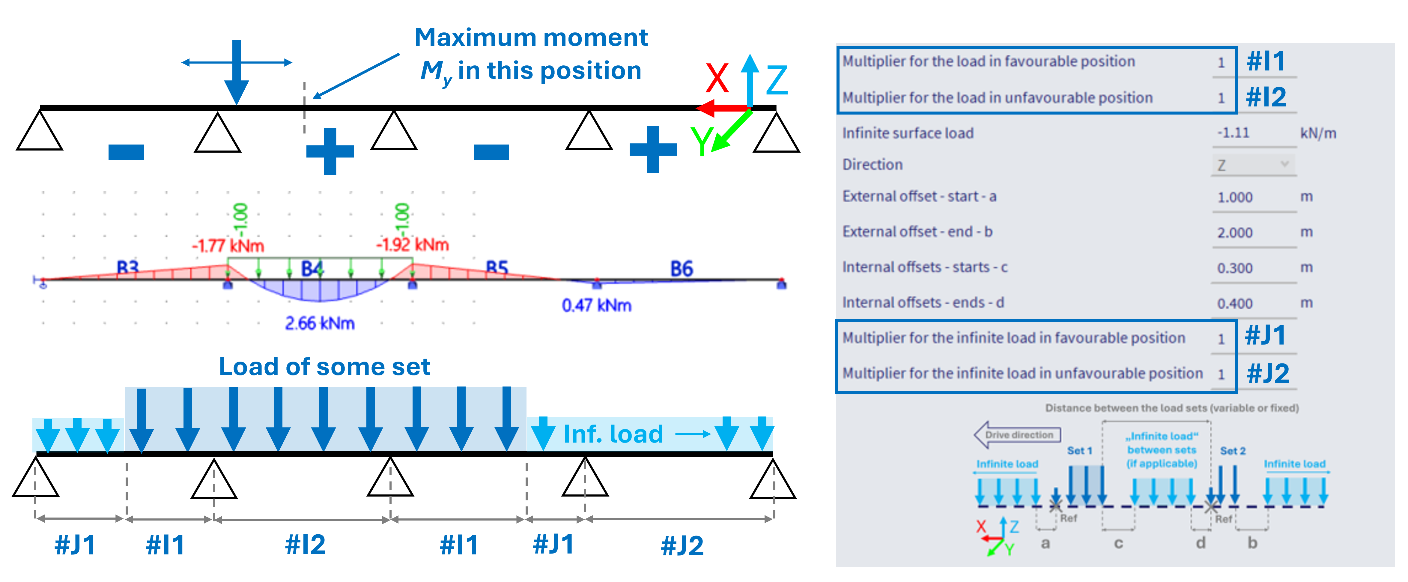
See example below - in case the extreme (positive) bending moment My is to be obtained in the middle of the second span on 4-span beam, the more load applied to 2nd and 4th span, the higher the moment. And vice versa. By setting the corresponding multipliers to 0, the load that would actually decrease the moment in this specific position is not considered at all, what would be much more conservative approach.
Notes of the features:
1) Load directions - #B, #C - for the Z direction, the load is considered in GCS z-axis direction, for X and Y directions, the loads are considered in the LCS system of the beams which determines the Traffic lane 1D. Keep this in mind in order to consider the loads correctly.
2) imagine the "sets" as vehicles moving in one lane. The axis of such lane is the "load system 1D", consisting of these sets. In order to consider several parallel lanes on one beam, or for example a crane which loads two parallel beams further away from each other (two distinct1D Traffic lanes) - this needs to be handled by either several load systems, or perhaps one load system assigned to several traffic lanes. This procedure is handled in subsequent step of the work flow, in Moving loads generator 1D. Examples are provided in this chapter.