Accidental Eccentricity
Introduction
Most of the seismic standards require that structures are checked for torsion due to mass eccentricity including an additional eccentricity – so-called accidental eccentricity. This is required to cover inaccuracies between the real structure and the modelization, as well as the fact that masses that are linked to service loads may vary during the life of the structure.
Two types of eccentricity must be distinguished for the analysis: the structural eccentricity and the accidental eccentricity.
The structural eccentricity is the offset between the center of mass and the center of stiffness of the structure. It is part of the structure. In a simplified seismic analysis via 2D models, where typically the X and Y directions are analyzed separately, the impact of the structural eccentricity is taken into account by manually distributing the torsional effects on the structure. An additional safety factor is usually applied to the structural eccentricity to cover inaccuracies due to that simplified method.
When using a 3D modelization of the structure, the structural eccentricity is automatically taken into account due to the fact that the X and Y and linked and analyzed together, allowing torsional effects to appear directly in the analysis without having to add them manually afterwards.
The accidental eccentricity accounts for inaccuracies in the distribution of masses in the structure. Design standards usually take it into account as an additional mass eccentricity that is defined as a fraction of the size of the structure.
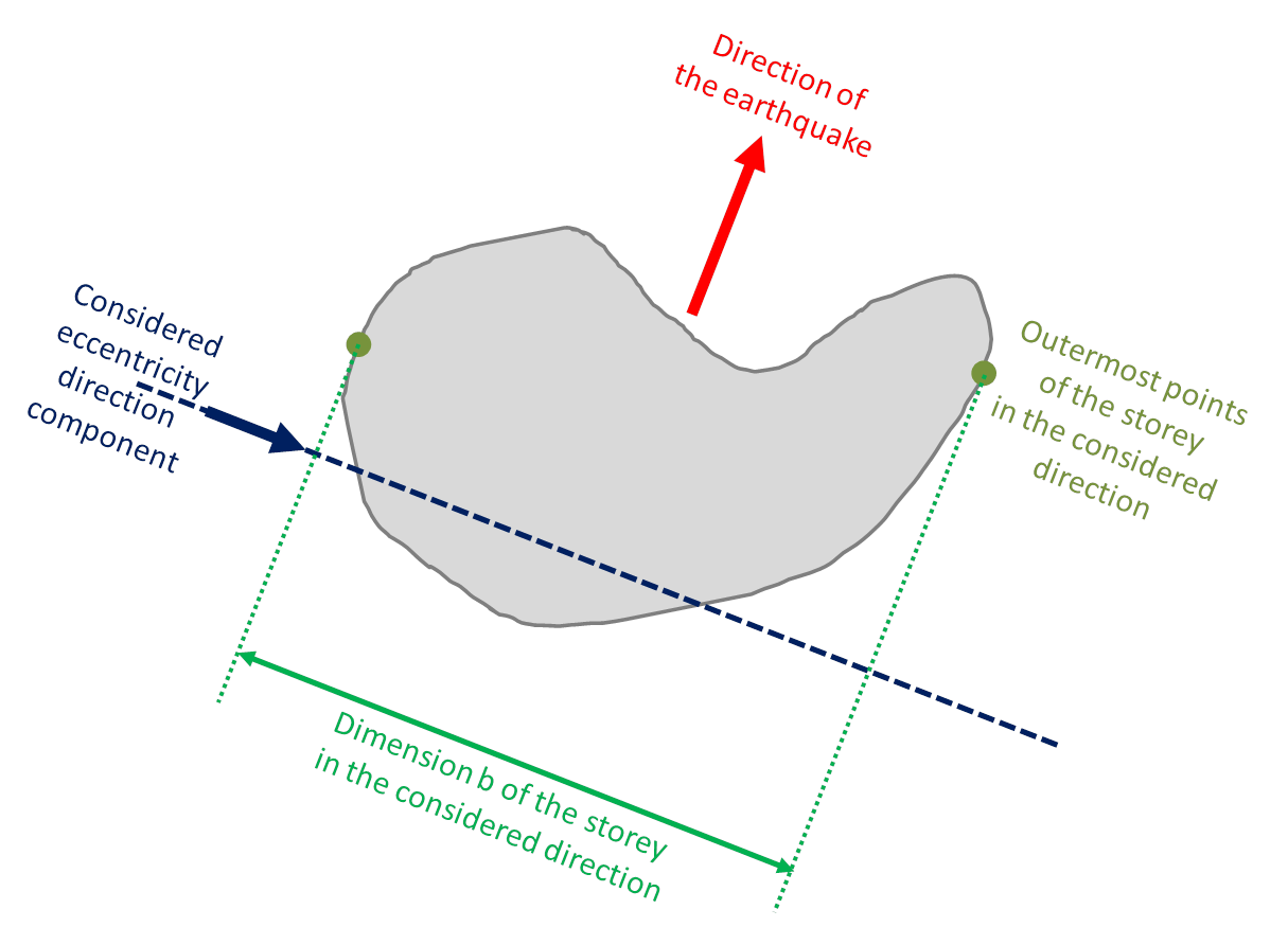
In the Eurocode 8, the accidental eccentricity for a given floor is defined as 5% of the width of the floor perpendicularly to the direction of the acting seismic action.
In simplified modelizations where the structural eccentricity appears explicitly, it is very simple to add the accidental eccentricity in the calculation. In general 3D modelizations, the structural eccentricity does not appear as such and it is therefore more complex to take its effects into account in such a case.
In SCIA Engineer, using the IRS condensed model allows introducing accidental eccentricity easily, since the condensed model uses only one R-node per storey. The accidental eccentricity may be taken into account either as real mass eccentricity or as additional torsional actions (simplified method according to the design codes).
However, the method using real mass eccentricity in the modal analysis has not been implemented yet in SCIA Engineer.
For now, only the simplified method using additional torsional moment is available.
Definition of the accidental eccentricity
First of all, please note, that accidental eccentricity may be used only together with the reduced model analysis. See how to enable it in Enabling the reduced model.
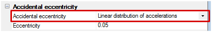
The accidental eccentricity settings are defined in the properties of the considered seismic load case, in the sub-group .”Accidental eccentricity”. Accidental eccentricity is disabled by default.
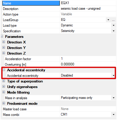
The method for the calculation of the accidental eccentricity can be selected in the combobox “Accidental eccentricity”:
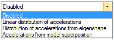
Depending on the selected method, various settings must be defined.
Eccentricity
value of the accidental eccentricity, defined as a fraction of the width of the considered storey in the direction perpendicular to the seismic action;
most seismic design standards specify a value of 0.05 for this ratio (EN1998-1 § 4.3.2(1)P and formula (4.3) ).
Mode shape
in case the distribution of accelerations is calculated according to a mode shape, the user must specify which mode should be used for that purpose
These settings are explained more in detail below.
Value of the accidental eccentricity
Regardless of the selected method, the value of the accidental eccentricity must be specified. That value is defined as a fraction of the width of the considered storey in the direction perpendicular to the seismic action (EN1998-1 § 4.3.2(1)P).
The actual eccentricity is then calculated as follows:

where eAr,i is the user defined value of the relative eccentricity, e.g. 0.05, and bi is the width of the considered storey. The value eA,i is computed separately for each storey.
Calculation of the effects of eccentricity
The accidental eccentricity is taken into account as follows:
- a dynamic analysis of the structure is performed without accidental eccentricity, using the response spectrum method
- the effects of accidental eccentricity are added by applying static torsional moments to the structure about the vertical axis of each storey. This method is described in detail in the Eurocode 8 (EN1998-1 § 4.3.3.3.3)
The general principle for the calculation of torsional moments is as follows:


where
Fj is the horizontal force acting on storey j
Fbase is the total horizontal force acting on the structure (aka base shear) in the considered earthquake direction obtained from the response spectrum analysis of the structure
mj is the mass of storey j
αj is the distribution key of the accelerations; this depends on the selected method; at this time, 3 methods are offered to define the distribution of accelerations (see below)
eA,j is the accidental eccentricity of storey j, as defined in the previous paragraph
Mz,j is the applied torsional moment about the Z-axis for the storey j
About accidental eccentricity and ELF seismic analysis: when the ELF method is selected for the seismic analysis, the storey forces are directly obtained from the ELF calculation. In that case, the method for the distribution of accelerations for accidental eccentricity can only be the same as the method selected for the ELF calculation.
Linear distribution of accelerations
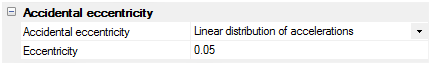
In this case, the distribution of acceleration is assumed to be linear, proportional to the height. The reference level is the overturning level defined in the seismic load case properties.
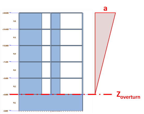

where zj is the level of the mass center of storey j. zoverturn is defined by the user in the properties of the seismic load case.
This method corresponds to the simplified approach defined in EN1998-1 § 4.3.3.2.3(3) and formula (4.11).
Distribution of accelerations from eigenshape
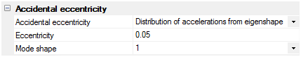
In this case, the distribution of accelerations is assumed to be proportional to the displacements of the structure in the relevant mode shape. The user must specify the reference mode (fundamental mode).
When the mode shape selection is set as “automatic”, the program selects the mode that has the highest modal mass in the direction of the seismic action.
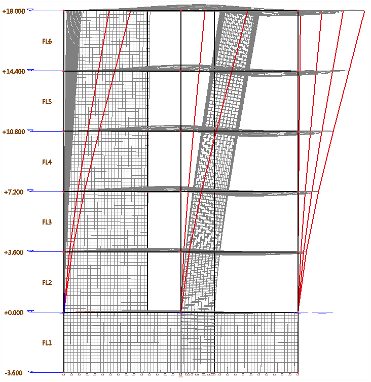

where UG,j is the modal displacement of the mass center of storey j in the direction of the seismic action, obtained from modal analysis of the reduced model.
This is the preferred approach in Eurocode 8, defined in EN1998-1 § 4.3.3.2.3(2) and formula (4.10).
Accelerations from modal superposition
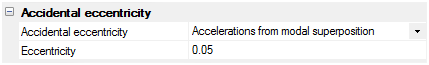
In this case, no distribution key is used. The accelerations are obtained directly from the seismic load case after modal superposition. The acting forces on storeys are obtained as follows:

where aGj is the acceleration at the mass center of storey j in the direction of the seismic action obtained from the modal superposition in the reduced model.
This approach is not described in the Eurocode 8. It is more conservative than the other approaches, as it uses an envelope of accelerations instead of a distribution of the resultant base shear. However, it has the advantage of covering cases where higher order modes cannot be neglected for accidental eccentricity.
Polynomial distribution of accelerations (ASCE 7-10 12.8.3)
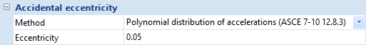
This method is available only when using the ELF method for the seismic analysis (static method). It is similar to the linear distribution method, but uses a different formula to calculate the vertical distribution of the horizontal acceleration. See the chapter about the ELF method for more details.
Analysis & results of accidental eccentricity
Accidental eccentricity load cases
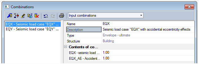
When enabling accidental eccentricity in a seismic load case, the program will automatically create an accidental eccentricity "slave" load case.
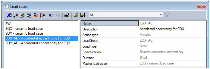
Accidental eccentricity load cases are read-only and cannot be deleted. To remove an AE load case, disable accidental eccentricity in the corresponding seismic load case.
All properties of AE load cases are read-only, except their name and description which may be edited by the user. The default values of the properties are:
Name
name of the source seismic load case with added suffix “_AE”
Description
“Accidental eccentricity for XXX” where XXX is the name of the master seismic load case
Action type
Variable
Load group
identical to Name; see next paragraph for details
Load type
static; the torsional effect is indeed computed as a set of static loads (moments) applied to the structure
Specification
Seismic accidental eccentricity
Duration
Short
Master load case
the master seismic load case; thanks to this, the accidental eccentricity will be applied in envelopes only when the corresponding seismic action is also present in the envelope
The content of an AE load case cannot be viewed nor edited. No loads can be added to it. The applied moments due to the accidental eccentricity are automatically computed during the analysis.
The generated AE load cases may be inserted in seismic envelope combinations in order to account for AE effects. Their results may also be viewed separately for validation.
Load groups
For each seismic load case with enabled accidental effect, the program will create automatically a read-only load group with the following properties:
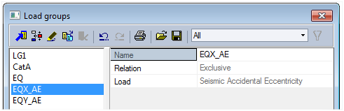
Name
same as the corresponding AE load case
Relation
same as the relation of the load group of the source seismic load case
Load
Seismic accidental eccentricity
This load group is automatically assigned to the corresponding AE load case.
Combinations
When using an AE load case in an envelope combination together with its source seismic load case, it will automatically be combined with the seismic action, assigning + and – sign to it. The AE load case will not be taken into account without its source seismic load case.
The AE load cases must be added manually to combinations.
A typical use case:
| Possible combinations | |||||||
|---|---|---|---|---|---|---|---|
| LC | Description | 1 | 2 | 3 | 4 | 5 | 6 |
| SW | Self weight (static) | 1 | 1 | 1 | 1 | 1 | 1 |
| EQX | Seismic load case (dynamic) | 1 | -1 | 1 | -1 | 1 | -1 |
| EQX_AE | Accidental eccentricity load case for EQX (static) | 1 | 1 | -1 | -1 | ||
Reminder: this table shows the principle of combination, but it is not applied strictly as such. When using a seismic envelope combination in checks, the program also uses for unsigned seismic load cases other cases where the sign of internal forces components are switched independently to account for the non-concomitance of extremes after modal superposition in the response spectrum method.
Reminder: when dealing with seismic load cases, for the reason above, use only “envelope” or “code” combinations. Do not use “linear” combinations, nor explode envelope or code combinations to linear.
Generated combinations
As mentioned previously, AE load cases must be added manually to load case combinations.
However, for convenience, the program generates automatically an envelope combination for each seismic load case, containing the source seismic load case and its AE load case and named after the source seismic load case. This allows to check easily the results for the full seismic action, including the effects of accidental eccentricity.