Equivalent Lateral Forces (ELF)
Introduction
Seismic ELF analysis is the most well known method for the seismic analysis of structures. Although it is quite conservative, its simplicity makes it a very popular method for seismic design.
The ELF method is a static analysis method. However, using it in SCIA Engineer requires the input of some data related to dynamic analysis: masses and at least one combination of mass groups must be defined, as the calculation of the seismic equivalent lateral forces is based on the distribution of masses in the structure. The calculation of storey forces is based on the definition of storeys as well as on the reduced system, which must therefore be defined in order to allow using the ELF analysis.
Defining an ELF seismic load case
Pre-requisites - before creating an ELF seismic load case
- enable dynamics and seismic analysis in the project settings
- define masses and a combination of mass groups (same as for any dynamic load case)
- define storeys
- enable the reduced model
Then create an ELF seismic load case
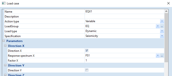
- create a new load case
- select Action type = Variable
- select Load type = Dynamic
- select Specification = Seismicity
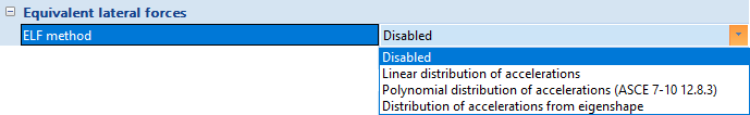
Then, in order to set the seismic load case to ELF, go to the settings group Equivalent lateral forces and select the desired ELF method (disabled by default)
A this point, most of the settings of a standard seismic load case will disappear from the dialogue, as many of them are relevant only for a dynamic response spectrum analysis. For an ELF load case, the following remain:
Direction X (resp. Y, Z)
Tickbox that enables the seismic action in the X (resp. Y, Z) direction
Response spectrum X (resp. Y, Z)
Selection of the seismic response spectrum for direction X (resp. Y, Z)
Factor X (resp. Y, Z)
Multiplying factor for the seismic action in direction X (resp. Y, Z)
Acceleration factor
Multiplying factor for the entire seismic action
Overturning
Reference level for the calculation of overturning moments. Also used as reference level when using a linear or polynomial distribution of accelerations
Accidental eccentricity
Accidental eccentricity settings act the same as for dynamic seismic analysis
Mass combi
Mass combination selected for the calculation of the seismic action
Specific settings for an ELF seismic load case
Equivalent lateral forces
ELF method
Defines how the distribution of accelerations will be calculated in the building. The various methods are detailed in the next section. The available choices are:
Disabled
ELF calculation of the seismic load case is disabled, i.e. the load case will use dynamic, multi-modal response spectrum analysis
Linear distribution of accelerations
The acceleration is increasing linearly with the global Z coordinate, starting with zero at the overturning reference level (see above)
Polynomial distribution of accelerations (ASCE 7-10 12.8.3)
The acceleration is increasing according to a polynomial function, according to ASCE 7-10 standard, starting with zero at the overturning reference level (see above)
Distribution of accelerations from eigenshape
The acceleration is distributed proportionally to the mode shape of an eigenmode selected by the user
Seismic force from
Defines how the total seismic force (base shear) is calculated. The available options depend on the selected ELF method.
Max acceleration of spectrum
The maximum acceleration of the selected response spectrum is used
Input fundamental period
The acceleration corresponding to a user input value of fundamental period is used
Selected eigenmode
The acceleration corresponding to the period of the user selected eigenmode is used; please note, that this implies a modal analysis of the structure
Approximate fundamental period (ASCE 7-10 12.8-7)
The acceleration corresponding to approximate fundamental period according ASCE 7-10 eq. 12.8-7. This is available only when ELF method = Polynomial distribution of accelerations (ASCE 7-10 12.8.3)
Fundamental period
User input fundamental period to be used for the calculation of the seismic force when Seismic force from = Input fundamental period
Mode shape
Eigenmode to be used for the distribution of the accelerations and/or the calculation of the seismic force
ASCE additional parameters
Structure type
This item is for values of approximate period parameters, see ASCE 7-10 table 12.8-2
Steel moment frame
Concrete moment frame
Steel eccentrically braced frames
Steel buckling-restrained braced frames
All other structural systems
Structural height from model
When this option is ticked, the structural height is obtained from the model as the maximal z-coordinate of top storey in project minus theOverturning reference level (Reference level for the calculation of overturning moments). When it is not ticked, the structural height must be defined manually.
hn (structural height)
Structural height of building, used for the calculation of the approximate fundamental period according to ASCE 7-10 eq. 12.8-7.
Ct
Coefficient for ASCE 7-10 eq. 12.8-7
x
Exponent for ASCE 7-10 eq. 12.8-7
Ta [s]
Approximate fundamental period, see ASCE 7-10 section 12.8.2.1 and equation 12.8-7
Limit fundamental period
When this option is ticked, the fundamental period used for the calculation of the seismic force is limited by the upper boundary value defined in ASCE 7-10 section 12.8.2 .
Cu
Coefficient for upper limit on calculated period, see ASCE 7-10 table 12.8-1
Maximum fundamental period [s]
Maximum fundamental period according to ASCE 7-10 section 12.8.2, defined as Ta multiplied by Cu.
Calculation of the Equivalent Lateral Forces
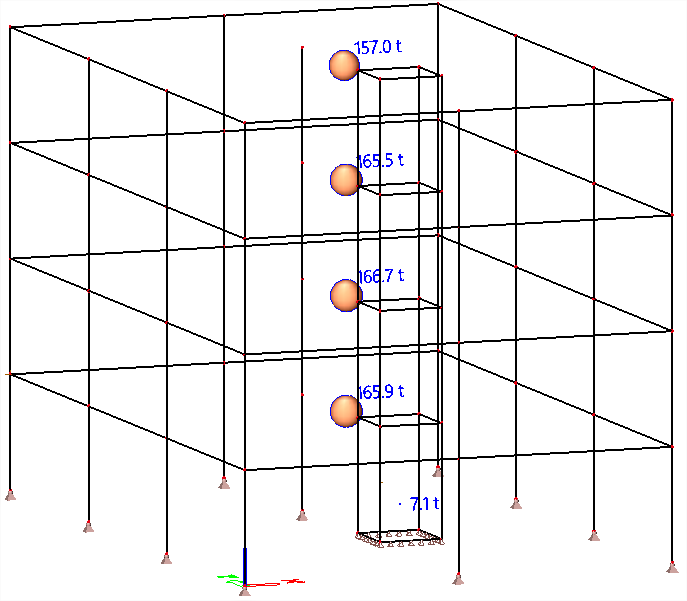
Equivalent Lateral Forces are applied as one concentrated force at the mass center of each storey of the building.
First, the total seismic force (base shear) is calculated. It is then distributed to the storeys according to the selected method (vertical distribution of accelerations). The same procedure is applied for each direction (X,Y,Z).
Calculation of the seismic force
The total seismic force Fbase is calculated as follows

where
Mtot is the total mass of the structure, obtained from the selected mass combination
aref is the reference acceleration, obtained from the selected seismic response spectrum
cdir is the direction factor defined in the seismic load case settings
cacc is the acceleration factor defined in the seismic load case settings
The value of aref is extracted from the response spectrum, according to the Seismic force from setting
Max acceleration of spectrum: the maximum value of acceleration defined in the selected spectrum
Input fundamental period: the value of acceleration corresponding to the period defined in the Fundamental period setting
Selected eigenmode: the value of acceleration corresponding to the period of the eigenmode selected in the Mode shape setting
Approximate fundamental period (ASCE 7-10 12.8-7) : the value of acceleration corresponding to the calculated approximate fundamental period
In the 2nd and 3rd cases above, the used fundamental period may be reduced by the calculated upper limit, if Limit fundamental period is ticked
Additionally, when a seismic response spectrum according to ASCE 7-10 is used (spectrum generator for IBC standard), the reference acceleration aref cannot be less than the specified minimum acceleration according to section 12.8.1.1:

where

additionally, if S1≥0.6 the following applies:

The parameters SDS, S1, Ie and R are defined in the settings of the IBC response spectrum generator.
g is the acceleration of gravity, defined in the project settings.
Distribution of the seismic force to the storeys
The storey force for the j-th storey j is calculated as follows

where
Fj is the horizontal force acting on storey j
Fbase is the total horizontal force acting on the structure (see above)
mj is the mass of storey j
αj is the distribution key of the accelerations, according to the selected ELF method setting
Linear distribution of accelerations
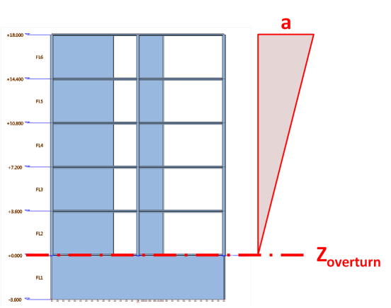

where
zj is the level of the mass center of storey j
zoverturn is the Overturning reference level, defined by the user in the properties of the seismic load case.
This method corresponds to the simplified approach defined in EN1998-1 § 4.3.3.2.3(3) and formula (4.11).
Polynomial distribution of accelerations


where
zj is the level of the mass center of storey j
zoverturn is defined by the user in the properties of the seismic load case
T is the reference fundamental period, depending on the selected Seismic force from setting:
Max acceleration of spectrum: T is unknown, the conservative value k=2 is used
Input fundamental period: T is the period defined in the Fundamental period setting
Selected eigenmode: T is the period of the eigenmode selected in the Mode shape setting
This method corresponds to the approach defined in ASCE 7-10 section 12.8.3
Distribution of accelerations from eigenshape

where
UG,j is the modal displacement of the mass center of storey j in the direction of the seismic action, obtained from modal analysis of the reduced model.
This is the preferred approach in Eurocode 8, defined in EN1998-1 § 4.3.3.2.3(2) and formula (4.10).
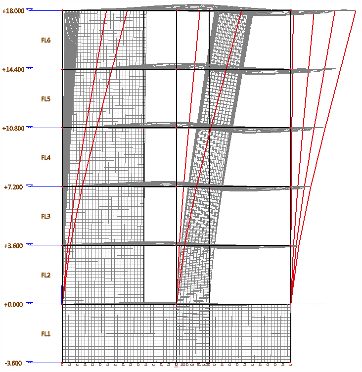
Application of the storey forces to the model
The calculated storey forces are applied to the structure using the reduced system. The transformation matrices of the IRS method allow to "smear" the concentrated storey forces in such a way that the resultant of each storey force is applied at the mass center of the corresponding storey. The loads are, however, applied in a distributed way to the entire storey, hence avoiding any numerical singularity, as would be the case if point loads would be applied in a conventional way.
Results
As an ELF load case is fundamentally a static load case, all standard result output can be used in SCIA Engineer, without restriction. Also, because it is a static load case, none of the issues related to the loss of sign due to the modal superposition apply here.
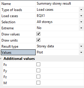
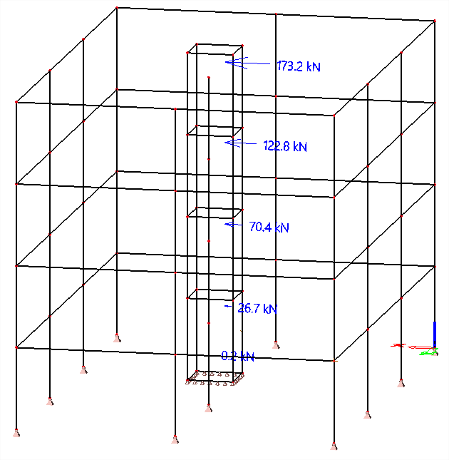
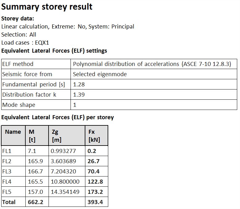
Additionally, the Summary Storey Results service allows to display the storey forces applied to the structure.