Design of cable members (PPE v16 and older)
Definition, application
'Cable' is special type of beam local nonlinearity which can be apply on 1D member in model. Thee feature can simulate special nonlinear behaviour of 1D member. For taken into account it is necessary to perform" Nonlinear calculation" .
Where to find it
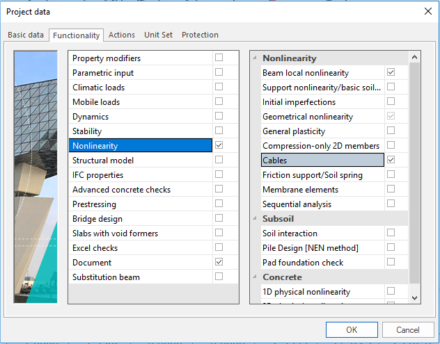
In project data dialog in part 'Functionality' it is necessary to switch ON 'Beam local nonlinearity' and 'Cables'. After that in standard tree in group 'Structure/Model data' there is possibility 'Beam - nonlinearity/Cable'.
How to create new one
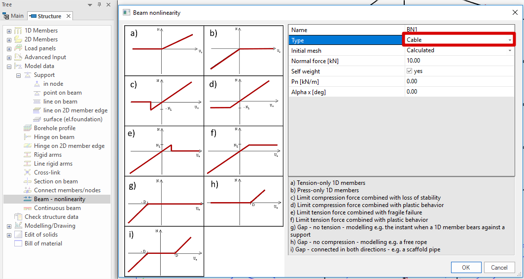
In 'Beam - nonlinearity' dialog there is possibility 'Cable' which can be set on 1D member.
When inserted into the model, a 1D member with this type of nonlinearity is marked by the following symbol (remember that in order to see the symbol, view parameters must be adjusted to show model data).

Parameters
|
Straight |
If ON, the 1D member is without any slack. Only the initial pre-stressing is then considered. |
|
Self-weight |
If ON, the slack cable is subject to self-weight. |
|
Normal force |
Specifies the value of the pre-stressing axial force. In order to take the normal force into account, the solver parameters must be adjusted accordingly - see below the table. |
|
Pn |
Specifies the value of the additional force. This parameter is ignored if Self-weight is ON. |
|
Alpha x |
Specifies the direction of the additional force. This parameter is ignored if Self-weight is ON. |
Normal force in the calculation
If the specified normal force is to be taken into account in the nonlinear calculation, the following parameters must be set in the Solver Setup dialogue (menu function Setup > Solver setup):
- Initial stress > Initial stress must be set ON,
- Initial stress > Initial stress as input must be set ON.
Note: If the parameter Initial stress as input is set to OFF, parameter Initial stress > Stress from load case must be specified as well. It selects the load case whose linear-calculation results are taken as the input stress.
Technical background
No special finite element is used for this type of analysis. Regular 1D member element is used, but its flexural stiffness is very very small. Small shear forces that appear during the iterative calculation appear are deleted.
Two cable elements can be modelled: (i) straight cable (pre-stressed element) and (ii) slack cable.
Straight cables
Only the pre-stressing force must be input for a straight cable.
Note: Proper settings must be made in Project Setup dialogue, Functionality tab. Options Initial stress, Nonlinearity, Beam local nonlinearity and "Geometrical nonlinearity" must be selected.
Slack cables
In addition to pre-stressing force, additional parameter must be defined for slack cable. The cable is subject to additional load: either (i) self-weight load, or (ii) a general load acting under the given angle and having identical orientation as the local rotation axis fix of the 1D member. These parameters are used to determine the slack of the cable in a particular direction. All calculations are carried out on the "deformed" structure. That means that the final deformation of a cable is calculated from this "slack" shape and not from the ideal straight shape of 1D member.
Note: Proper settings must be made in Project Setup dialogue, Functionality tab. Options Initial stress, Nonlinearity, and "Geometrical nonlinearity" must be selected. Option Beam local nonlinearity does not have be ON; it would lead to unnecessary lengthening of calculation.
Note: ONLY " Newton-Raphson method" can be used for this type of analysis." Timoshenko theory" MUST NOT be applied for analysis of slack cables.
Example
More details about cable members theoretical background: see Advanced cable analysis