Harmonic load cases
When the load type of some load case is set to dynamic, it is possible to set the specification of such load case to single harmonic load case or, in order to use automatic generation of several harmonic load cases, each with a different frequency from provided range, to set the specification to harmonic range load case.
In order to define the harmonic load cases, at least one combination of mass groups needs to be present in the project.
When harmonic load case is present in the project, harmonic analysis will be conducted.
During the harmonic analysis, it is assumed that all the applied loads vary harmonically (sinusoidally) with time. In order to specify a harmonic load completely, three pieces of information are required: the load amplitude, the phase angle of the load, and the forcing frequency of the load. The amplitude and the phase angle are defined for each load within the load case separately in the properties of each defined load (the defined load value is considered to be the amplitude). The forcing frequency is the same for all the loads within one load case, and defined in the load case properties (see the chapter harmonic load case).
Harmonic loads
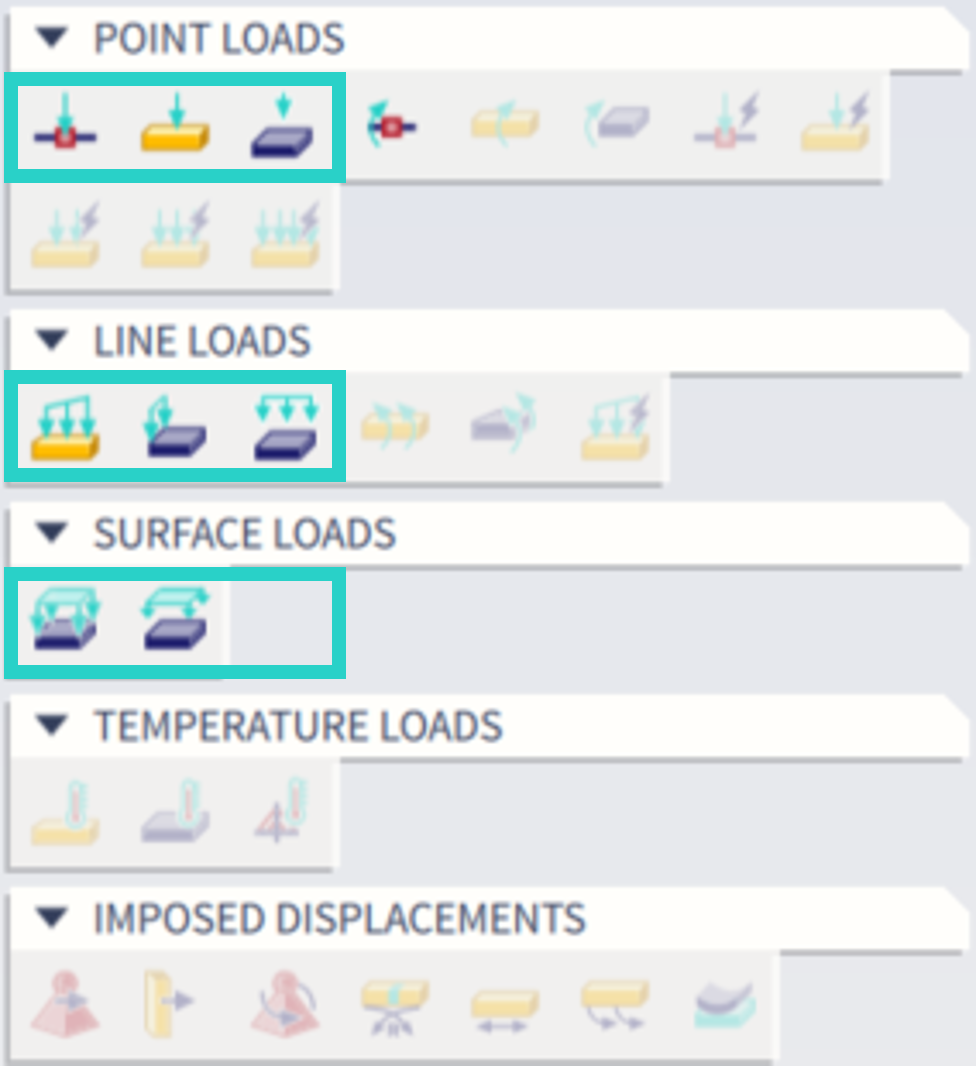
Once the specification of some load case is set to harmonic (no matter whether single harmonic load case or harmonic range load case), the supported load types to be defined within this harmonic load case are:
Point loads: point load in node, point load on 1D and free point load (note: also moment in node is allowed to be used. However, for this type of load, the phase angle property is not supported. It is theoretically possible to use the harmonic moment load, but the practical use is rare, and not so transparent. Hence it is rather recommended to use force load along with arm of this force in order to model the harmonic load properly)
Line loads: line load on 1D, line load on 2D edge and free line load (note: line moment loads are not supported)
Surface loads: surface load on 2D, free surface load
The supported load types are also summarized in the figure below:
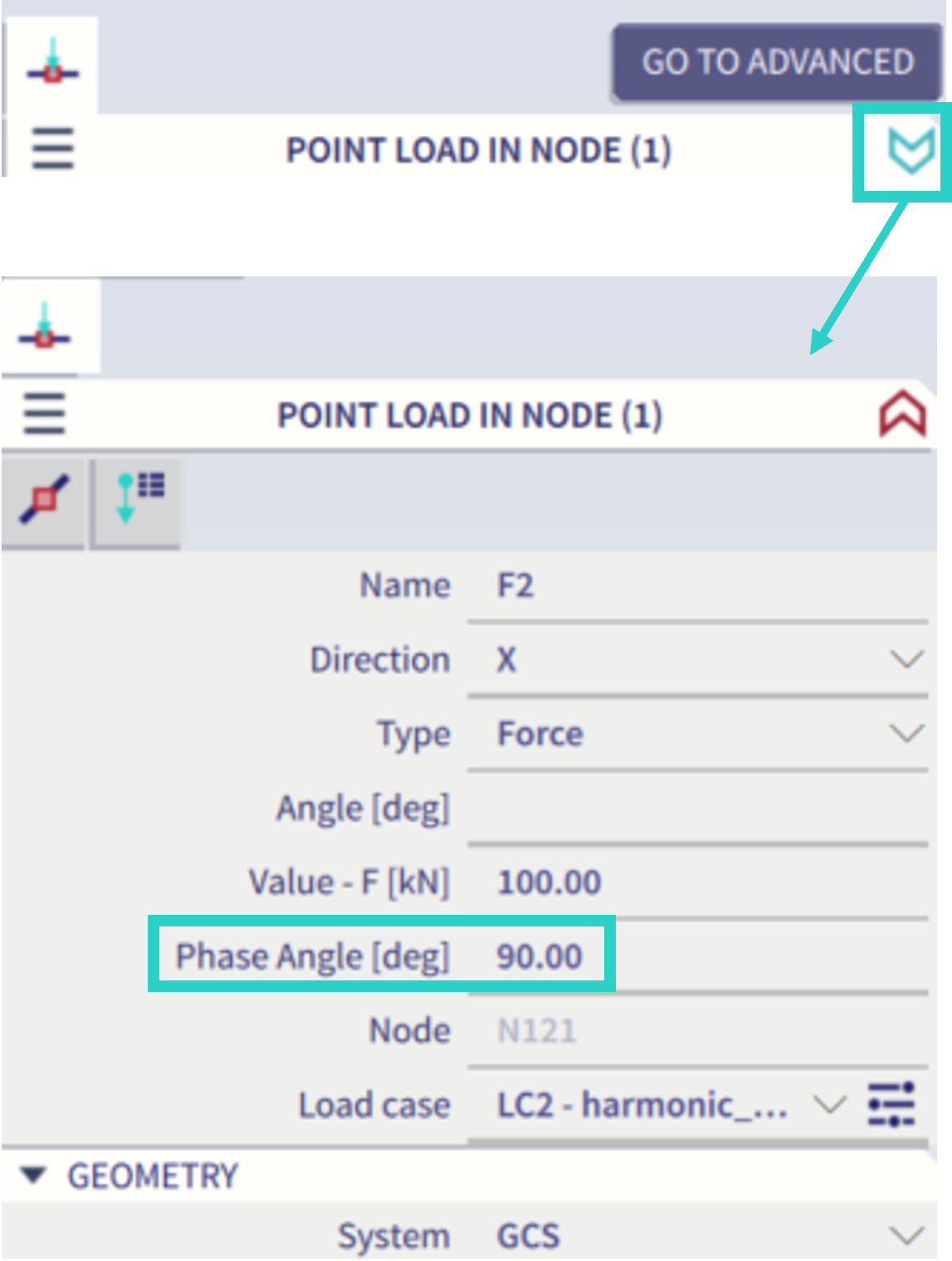
For each of these defined loads, it is possible to define a phase angle in the corresponding load properties. An example for the point load in node is depicted in the figure below. Note: in order to see this property of the "phase angle", the "advanced" view of properties needs to be activated (see the figure below).
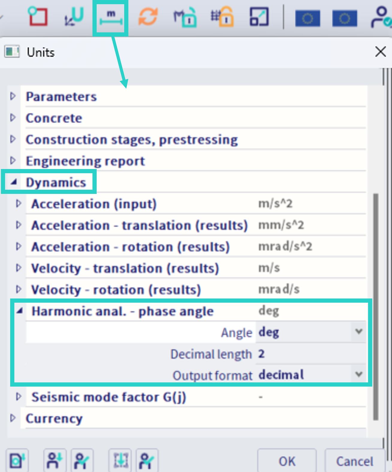
Note: the unit of the phase angle might be changed in: unit system - manage units - dynamics (see also the figure below). Available units are degrees, radians, miliradians and grads.