Harmonic load case (single load case)
Harmonic load case is a linear load case.
Properties of the harmonic load case
Method and damping
Method might be selected as Modal Superposition or Full Harmonic. For the Modal Superposition, both Rayleigh damping and also Constant damping are available to be selected as the "damping type" property. In case of the Full harmonic method, only the Rayleigh damping is supported.
Period division for summation
The response of the analysed structure during the harmonic loading is variable in time, altering periodically. In general, the results might be obtained from any time step of this period. The most critical results are the extremes (maxima in the absolute value). Hence, these extremes are provided as the results of the harmonic load case. The property "period division for summation" determines the step size of the periodical response from which these extremes are evaluated.
Available inputs are 6 numerical input values (6, 12, 24, 48, 72 and 360) and one string value named "amplitude summation". If the numerical values are input, the larger the value, the more exactly are these local extremes evaluated. On the other hand, the calculation of larger projects might take slightly longer. Recommended value for most projects is 48 or 72. Value of 6 is "too coarse" and might lead to not exact results. Value of 360 is on the other hand too fine, and will increase the size of the result files of the project, possibly slowing down the calculation as well.
The difference numerical inputs are explained in the example below.
Example of the various numerical input of the property "Period division for summation"
Let's assume a simple cantilever column, where the translation of the upper point in constrained in the GCS y direction. There is a mass of 100 kg in this point, and harmonic load of two forces (each 1 kN), one acting vertically and the other horizontally (with the phase angle of 90 degrees to simulate rotating force). The set up is depicted in the figure below. The mass of this structure is defined in 2 directions, hence it might be considered as with 2 DoF (degree of freedom) in the upper node.
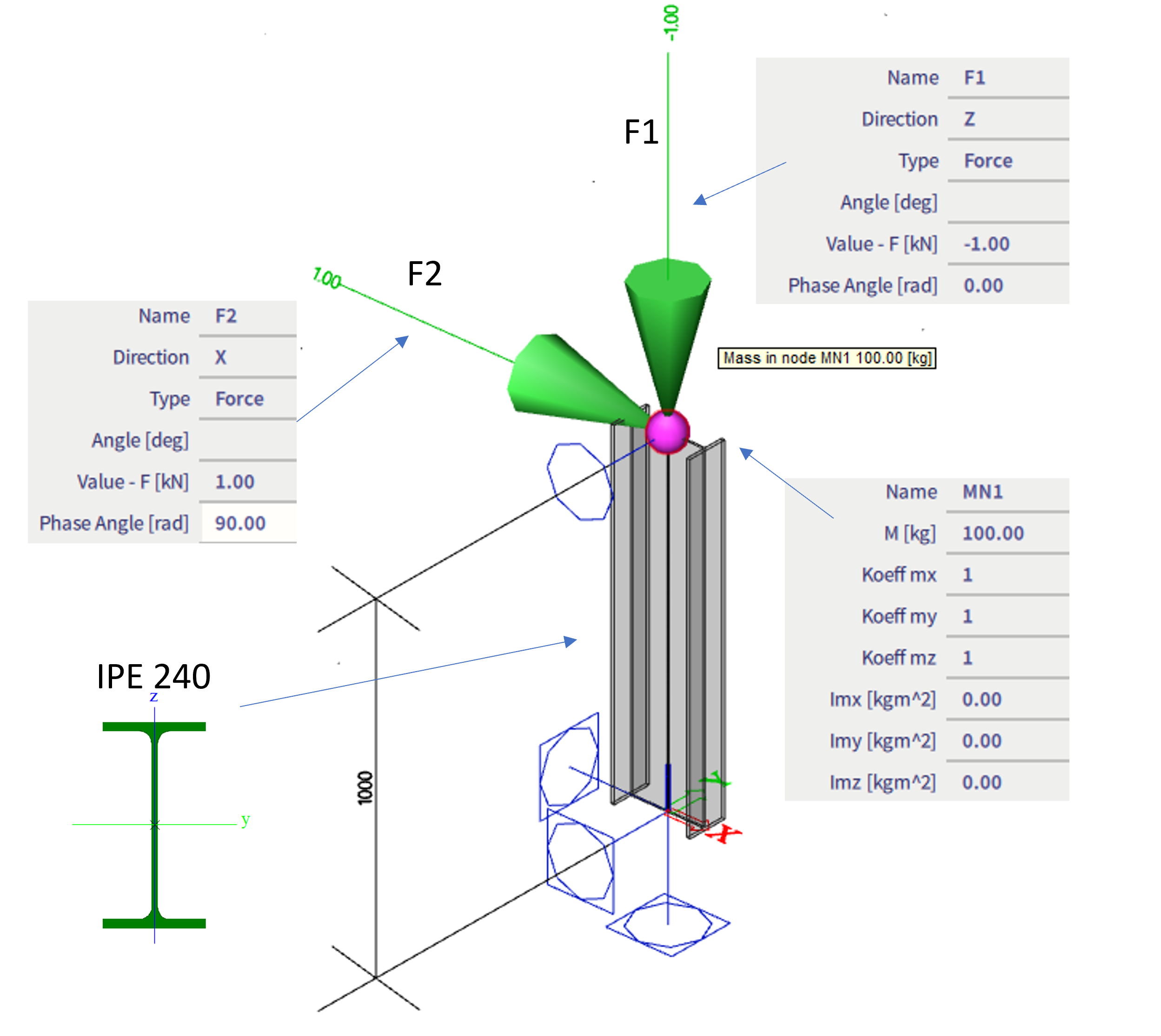
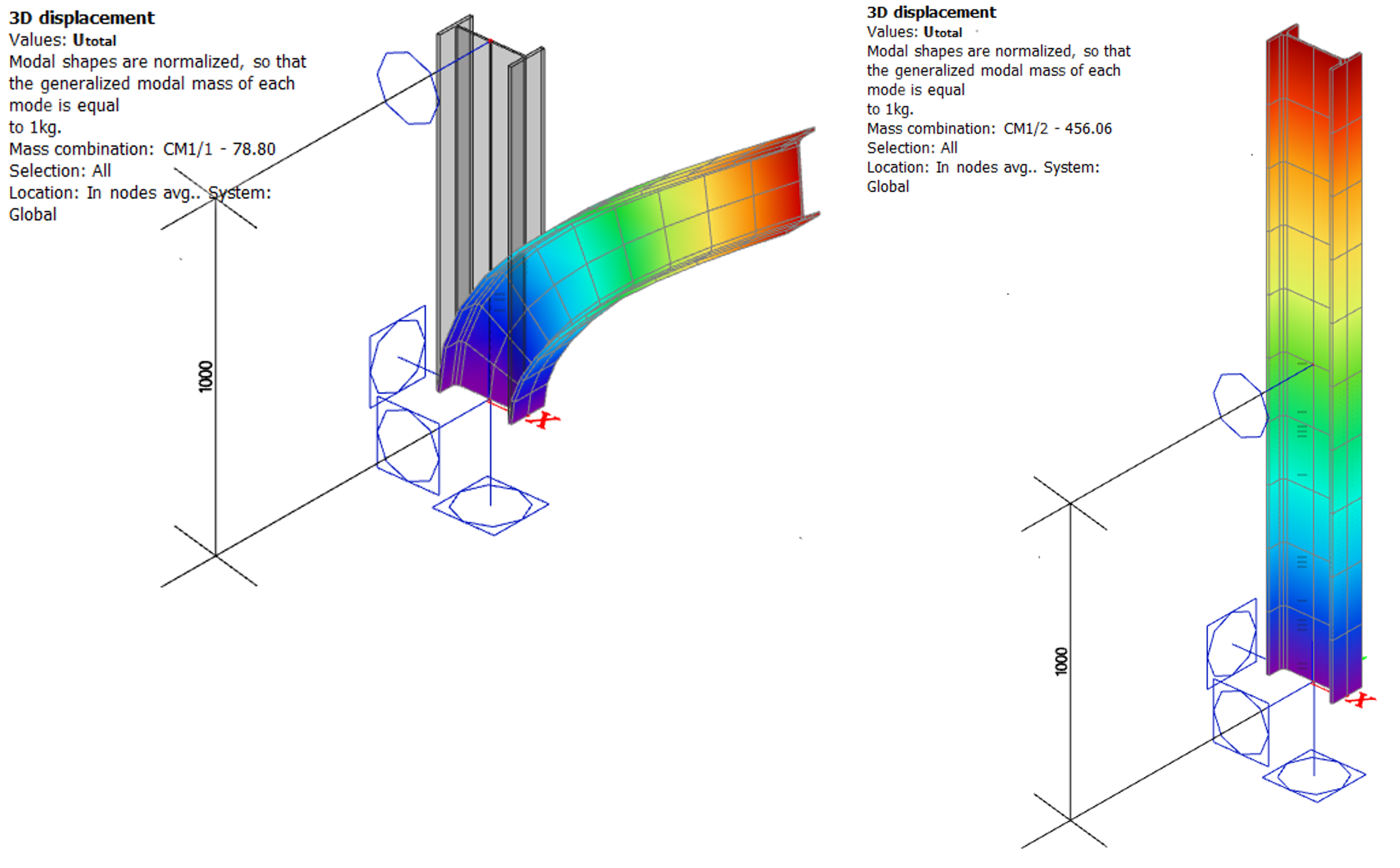
In case we neglect the mass of the column itself (not considering the mass based on the self-weight), and also neglect the deformation caused by the shear force (in order to make verification based on hand calculation easier), the two eigenvalues of this structure are 78.80 Hz (shape of translation is horizontally) and 456.06 Hz (vertical shape of translation).
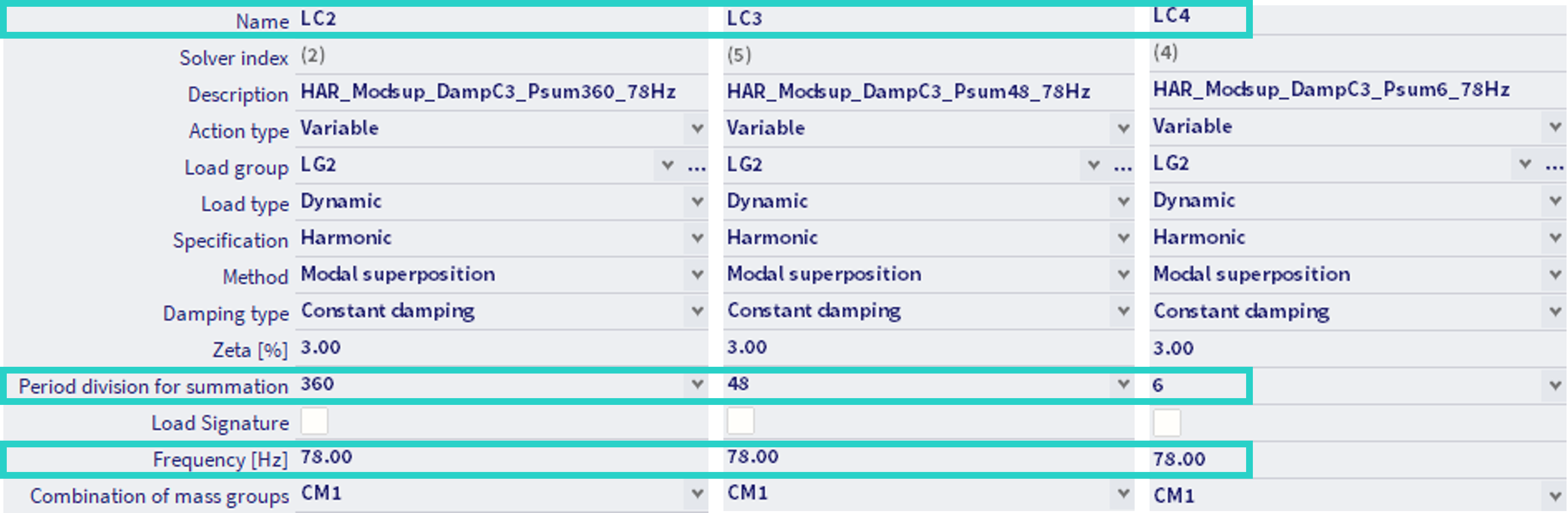
Let's define 3 harmonic load cases LC2, LC3 and LC4, each with the same frequency of 78 Hz (which is close to the natural frequency, so the results are nicely visible), and with property "period division for summation" equal to 360, 48 and 6 respectively, as depicted in the figure below.
The response of the structure loaded harmonically is periodical. Results provided by the FEM solver in the background are available for one period (more precisely half of one period, as the second half will be the same in absolute value). The property "period division for summation" defines the number, in how many time steps within one period are the results provided. These time steps are evenly distributed within the period. These results are then used by SCIA Engineer for the further post processing. Some examples are provided below. In the left part of each figure, there is the whole half period as provided by the FEM solver in the background of the software (in temporary files), in the right part of each figure there are the results provided graphically in 3D scene of the SCIA Engineer after processing.
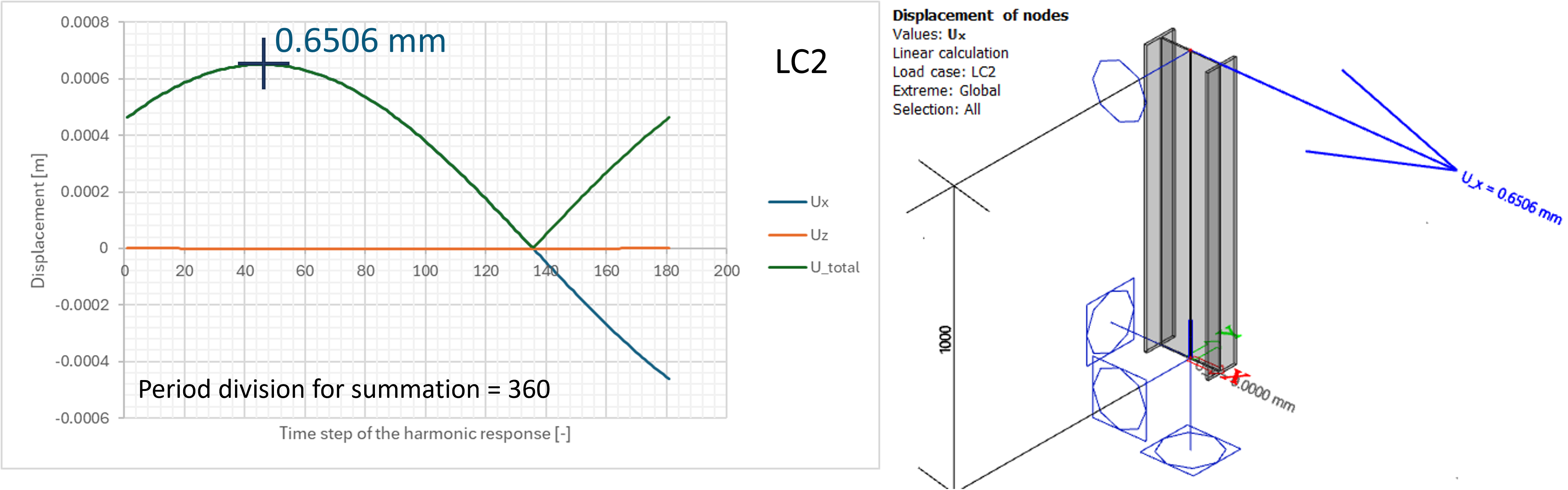
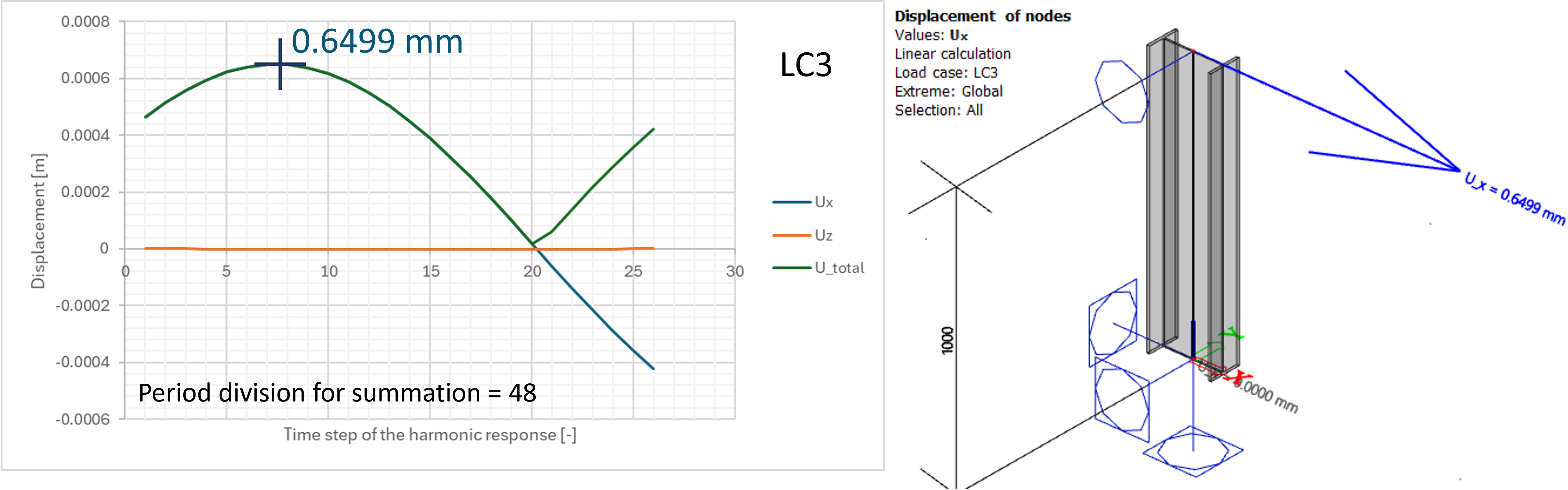
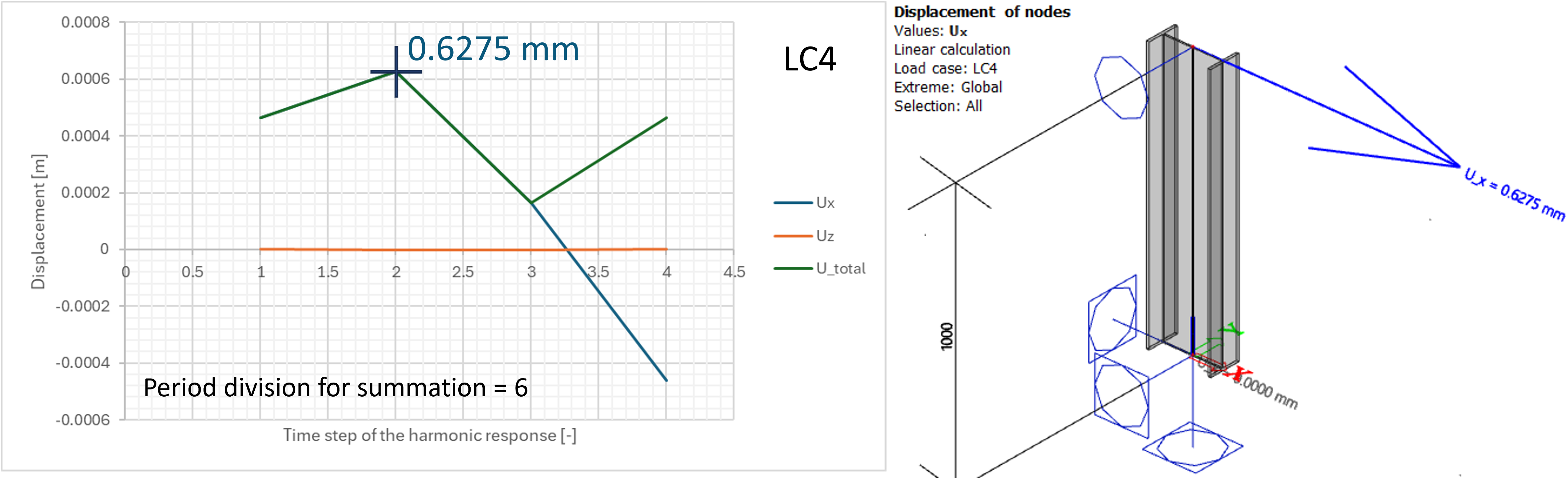
It might be observed, that when the results are desired to be provided in 360 divisions of the period (hence 180 divisions of the half of the period - as visible on the x axis of the uppermost example), the harmonic response is more smooth, and the maximum of the displacement in the x axis direction is approximately 0.6506 mm. When the results are provided in 48 divisions within this period (hence half the period of 24 divisions - or 25 points in time, as visible on the x-axis of the second example), the result is less exact, in the example 0.6499 mm, what is still very close to the more precise result. However, when the results are provided in only 6 divisions of the period (hence 3 divisions of the half period - what makes only 4 points in time), the local extreme is provided less precisely - in the example above, the value is 0.6275 mm, so the difference for the Ux value is less then 4%, what does not appear to be so significant neither. However, keep in mind, that also the total displacement Utotal is then processed in smaller number of the time steps. In the example above, the vertical displacement Uz is very small, as the eigenfrequency for this direction was much larger (456 Hz) than the currently analysed forcing frequency of the 78 Hz (which is near the resonance of the mode in the Uxdirection). However this might be different for different structure, different loading conditions and eigenfrequencies. Keep this in mind when conducting the harmonic analysis.
"Period division for summation" = "Amplitude summation"
If this option is selected, for all the results provided by FEM solver, the extremes are provided. These extremes are however provided for the results in the main GCS directions x, y and z, so for the displacements, results of Ux, Uy andUz will be the extreme values from the whole period. The value of total displacement Utotalprocessed by SCIA Engineer however might be (and most probably will be) obtained from the extremes of the Ux, Uy andUz each from a different time step of the period (hence the "amplitude summation"). The real value of the Utotal might be much smaller. However, in dynamic analysis it cannot be said in general that if the "larger" result is considered, the design will be more safe. On the other hand, the most precise solution is rather required.
Note: this option is also present, as in the past versions of the SCIA Engineer (the old harmonic analysis from 32 bit version of the software) automatically used this approach. Therefore, if the results from past version (32 bit harmonic analysis) are to be compared with the results of harmonic analysis conducted since SCIA Engineer version 25, this option "amplitude summation" needs to be selected for the property of "period division for summation".
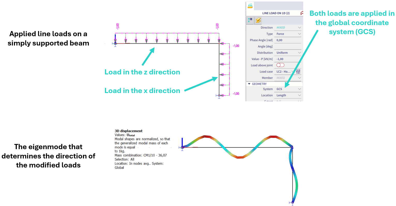
Load signature
The load signature is used to automatically modify the loads in the load case so that their direction (positive or negative) corresponds to the shape of the selected eigenmode. In order to achieve this two parameters have to be defined. The first is "Mode for load signature", where any of the available eigenmodes can be selected. The shape of the eigenmode defines the areas on the structure where the modified load will have a positive or negative direction. The second setting is "Affected load direction", which allows to choose in which global direction the load will be modified. The available directions are x, y and z.
To ensure that the "load signature" works correctly, both parameters mentioned above must be defined properly and the load must be defined in the global coordinate system (GCS). Load will not be modified if any of the following scenarios occur:
-
The load is defined in the local coordinate system,
-
The load is applied in a different global direction than that specified in the affected load direction setting, and the deflection of the selected eigenmode is zero in this direction,
-
The load and the affected load direction have the same global direction, but the deflection of the selected eigenmode is zero in this global direction,
-
The load is applied in the direction of deflection of the eigenmode, but the affected load direction is selected in a different global direction.
In the case of 2D elements, the user has the possibility to check the modified load by using Surface Loads (2D results). These results allow to see the load distribution on the surface. The determination of the modified load for 1D and 2D members is described in the examples below.
Example - 1D member
For simplicity, a simply supported beam loaded with a linear load is considered. It is required to modify the applied load according to the 2nd vertical bending eigenmode (4th eigenmode in SCIA Engineer).
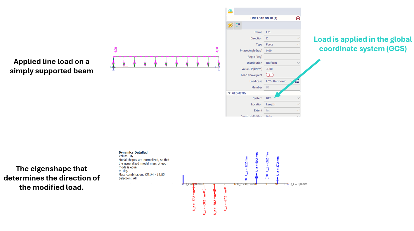
To achieve the required modification of the load, it is necessary to make the following settings in the load case:

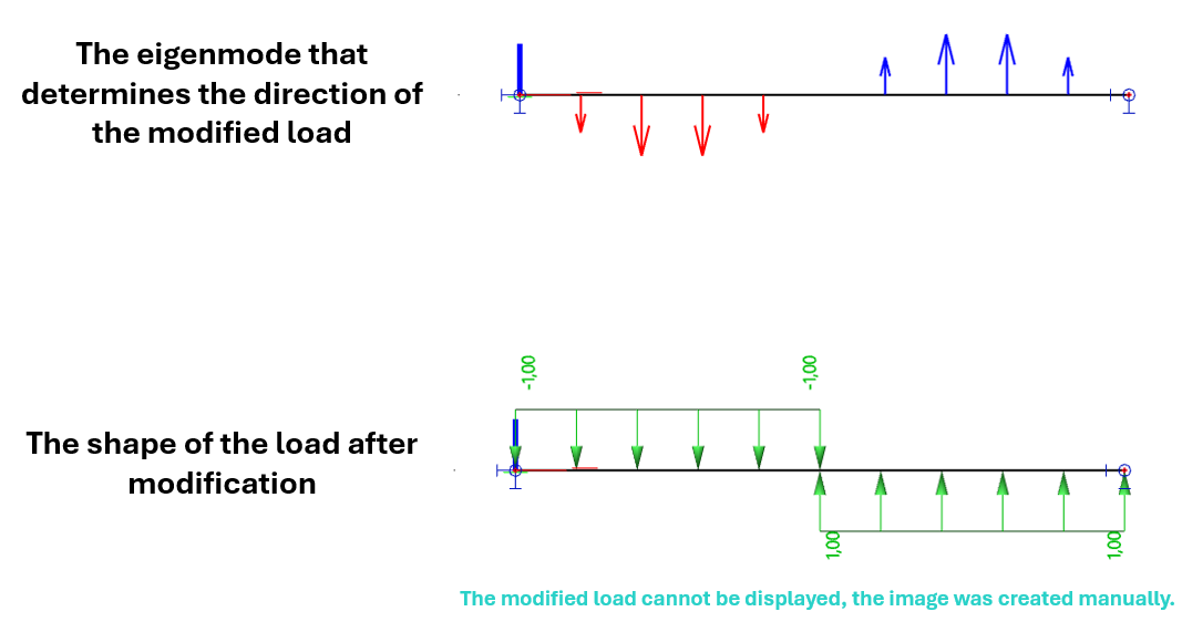
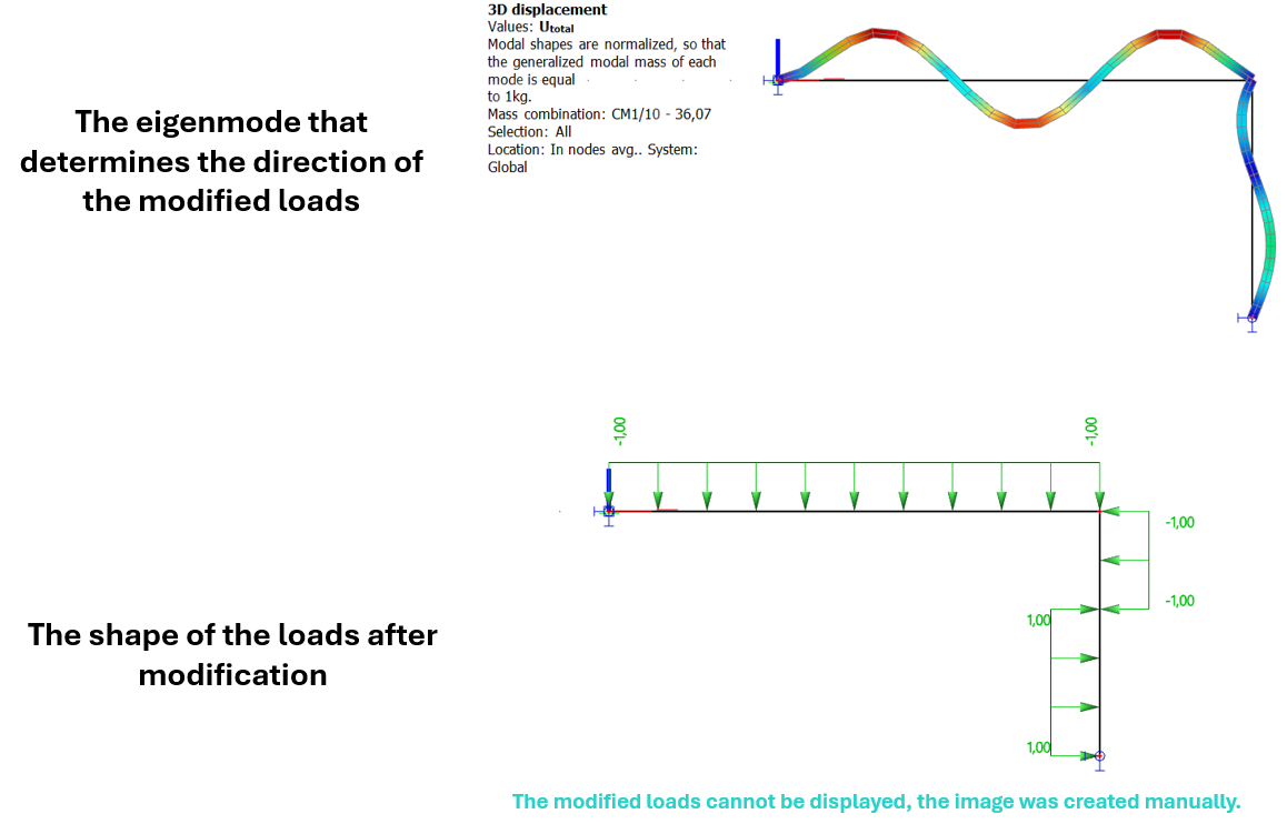
From the figure above, it can be seen that modification of the load in load case LC2 is required according to the 4th eigenmode. The generated load cannot be graphically displayed in the SCIA Engineer. Its modification is done in the background during the calculation of the load case by FEM solver. For the purpose of the example, a visualization of the resulting load shape is manually created. In an element where the eigenmode changes sign from positive to negative values (or vice versa), the length of the positive and negative parts is calculated by using linear interpolation between the values of the deflection on the element nodes.
Verification of the implementation of the load change is possible by means of the results (e.g. Dynamics detailed). For example, the shape of the displacement after the calculation with the modified load corresponds to the selected 4th eigenmode.

Example - 1D member
The purpose of this example is to show how the choice of the affected direction influences the load modification. For the purpose of the illustration, the structure shown in the figure below has been selected. It will again be loaded with a continuous linear load. The requirement is to modify the load in the x-direction according to the 10th eigenmode.
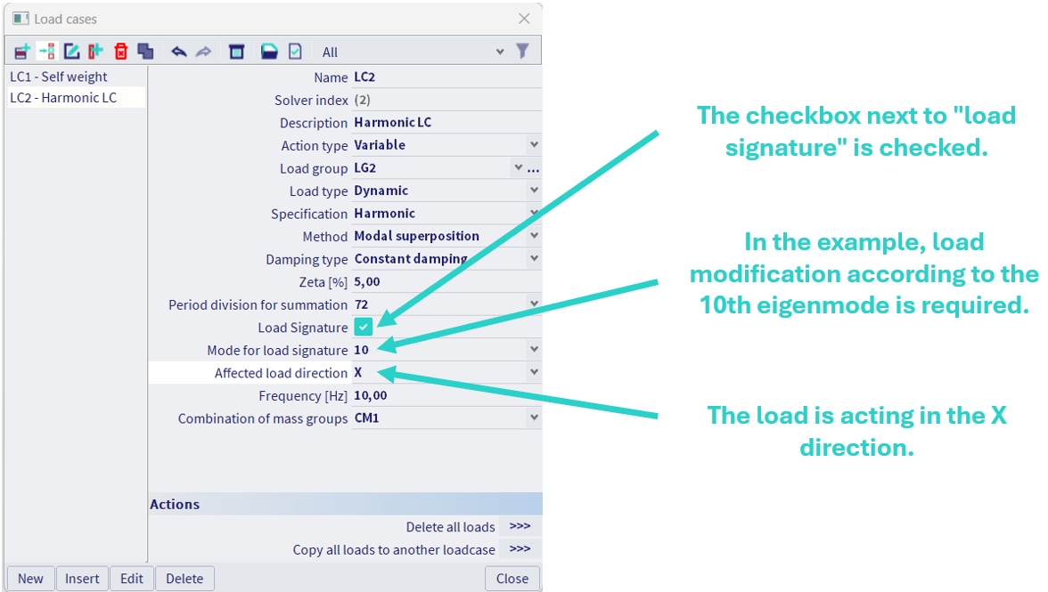
Since we have selected only one direction in the load signature settings, the load acting in the other directions remains unchanged.
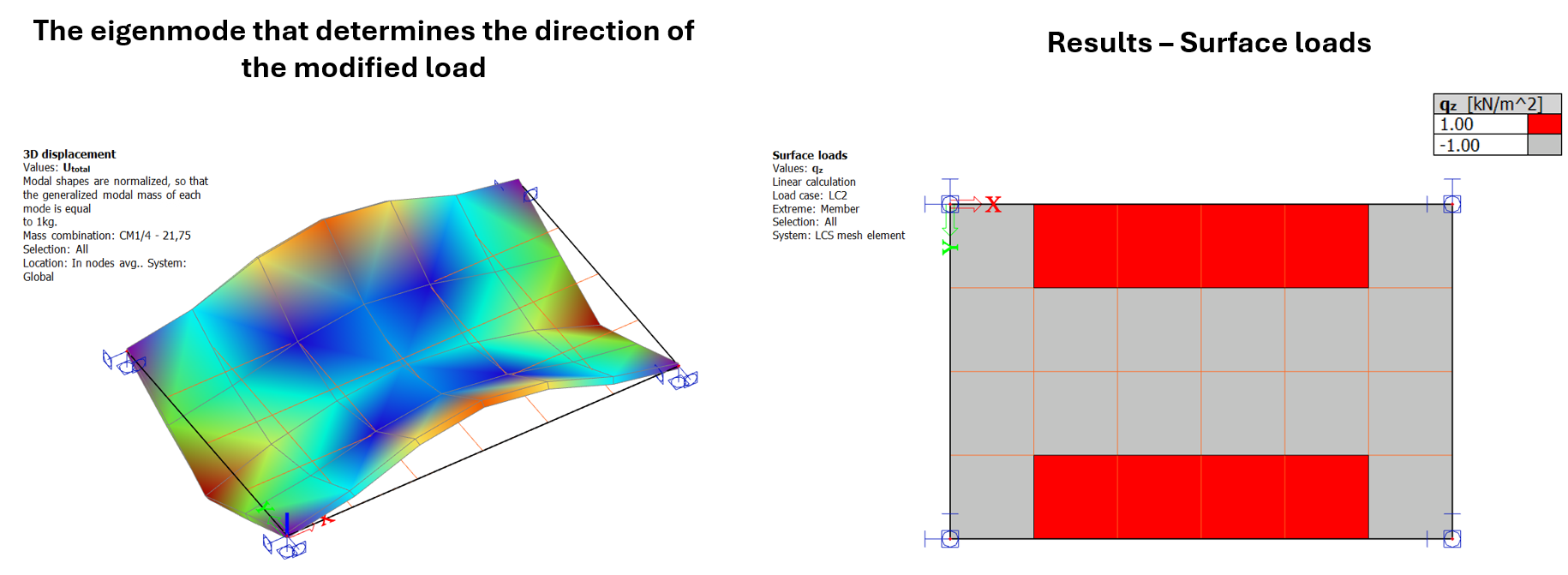
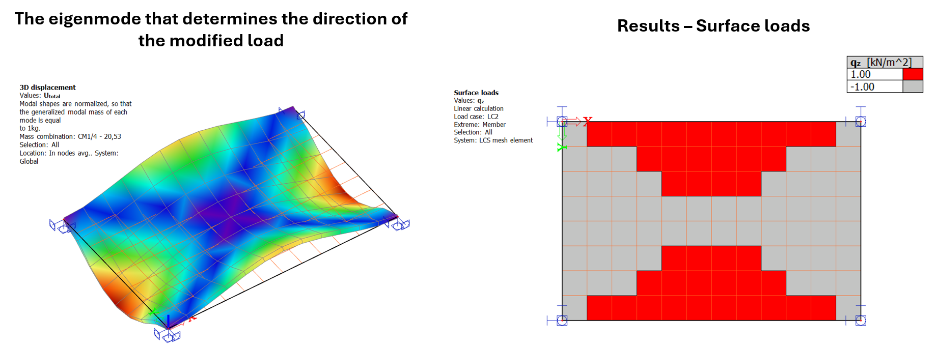
Example - 2D member
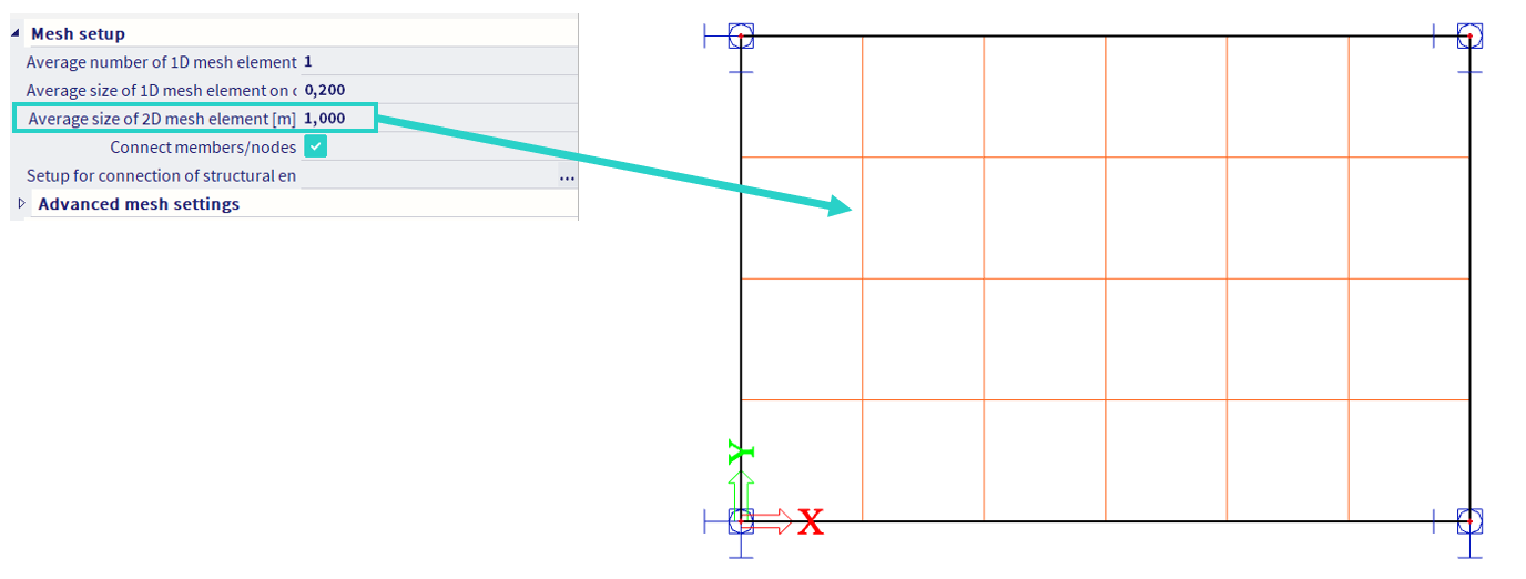
For 2D elements, the setting of the load case is identical to the 1D elements (see example above). However, there is a difference in the calculation of the length of the generated load in areas where the sign of the eigenmode changes from positive to negative (or vice versa). In the case of a 1D element, the length of the positive and negative parts of the element is calculated (so one element may contain a positive force value at the beginning and a negative force value at the end. For 2D elements this calculation is not performed and each element has only one sign (the force has either a positive or negative direction). Hence, the accuracy of the load modification depends on the element mesh setup (the smaller the elements, the more accurate the load created). If the element has a zero value for the deflection of its own shape, the modified load has the same sign as the original ( applied) load.
To demonstrate the load modification, we use a plate that is rigidly supported at its corners. The plate is loaded with a surface load. Modification of the load in the Z direction is required according to the 4th eigenmode.

In the first case, the element mesh is set with an element size of 1 meter (in the following figure, the finite element mesh is shown by a solid orange line). The value of the modified load on the 2D element can be checked in SCIA Engineer using Surface Loads (2D results). It can be seen that on each element the load has either a positive or negative direction.
In the second example, the grid is set up with an element integrity of 0.5 meters. Looking at the figure below, it is clear that the layout better matches the 4th mode shape.

Load signature works for both the quadratic and triangular mesh.
Frequency
The forcing frequency of each load within certain harmonic load case is considered to be the same value, and is defined directly in the load case properties.
Note: the unit of the forcing frequency might be changed in: unit system - manage units - others - frequency. Available units are hertz, kilohertz and megahertz (Hz, kHz, MHz respectively).
Combination of mass groups
For each harmonic load case, a specific combination of mass groups needs to be assigned.
If the Modal Superposition method is considered, the corresponding eigenmodes from the prior modal analysis of the selected combination of mass groups will be used for the harmonic analysis.
If the Full Harmonic method is considered, masses based on the selected combination of mass group will be considered for the analysis process (in this case, the prior modal analysis is not required), but it will still be calculated in the background.