Harmonic range load case
Harmonic range load case is very similar to the single harmonic load case. It contains the same properties, and the logic of applying loads within the harmonic range load case is the same as in the single harmonic load case.
In harmonic range load case, the "input load case" and the subsequent "result load cases" are distinguished.
Harmonic range "input" load case
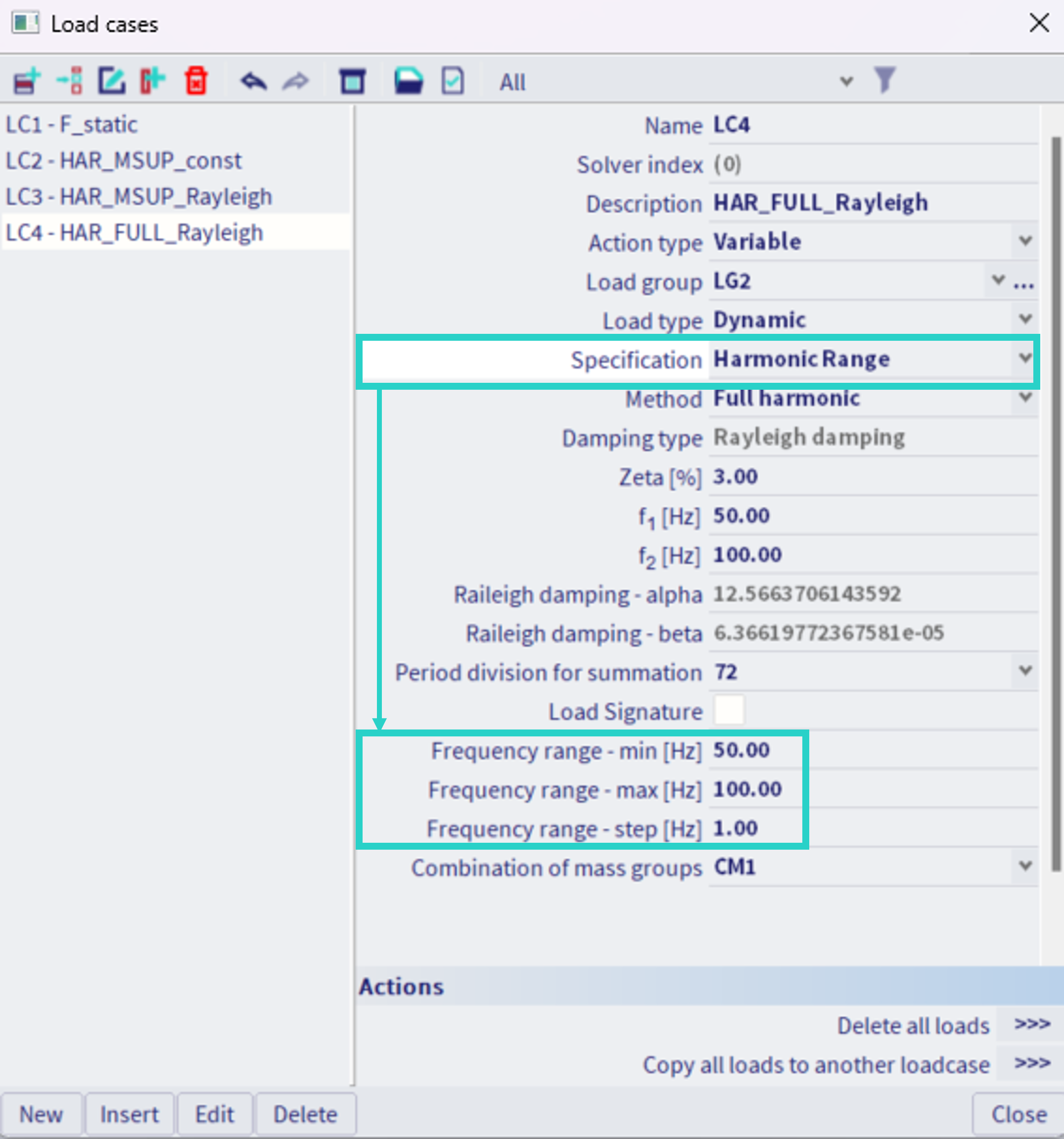
In the "input load case", the properties are set by the user along with the desired frequency range. All the loads are also applied within this input load case (which behaves the same way as the single harmonic load case. The supported loads are summarized in the chapter harmonic load cases).
The purpose of harmonic range load case is to automatically generate multiple harmonic load cases (the "result load cases") with the same settings, but different forcing frequencies. Hence, instead of the single frequency input (as in case of the single harmonic load case), the user needs to input the range of frequencies and the desired frequency step within the "input load case".
An example is provided in the figure below. The range is defined by the minimal and maximal value (in example 50 and 100 Hz respectively), and the step (in the example 1 Hz).
Harmonic range "result" load cases
Once the harmonic analysis is initiated, so called "result load cases" are automatically generated, based on the defined frequency range. After the calculation is finished, it is possible to check these result load cases also in the library of the load cases - see the example below.
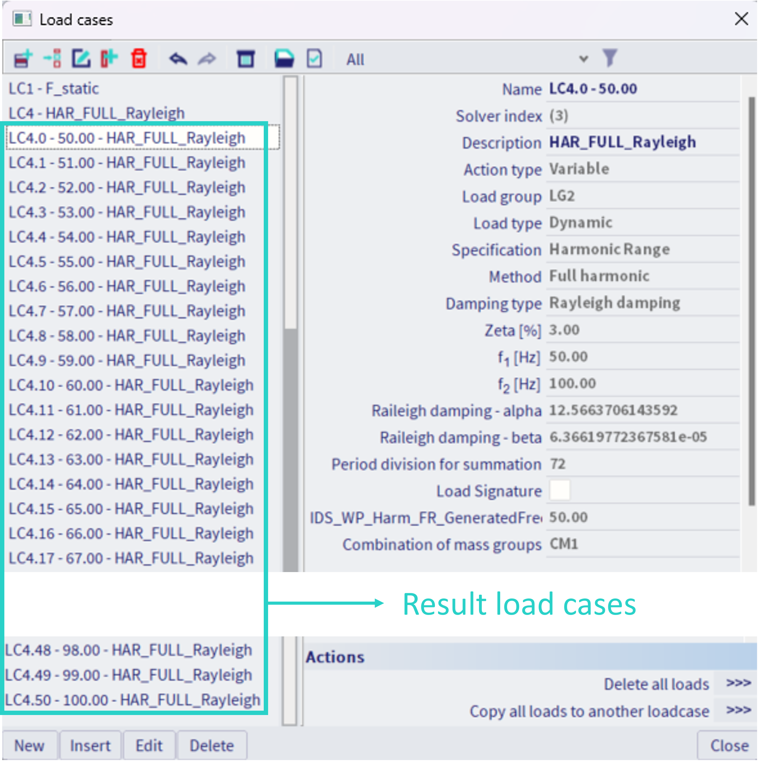
in this example, with range from 50 to 100 Hz and step of 1 Hz, 51 result load cases have been automatically generated and numerically analysed. The names of these result load cases are based on the name of the input harmonic load case, with addition of the load case number after the dot symbol (starting with 0), following by the specific frequency value (see example in the figure above, where the name of the input load case was "LC4", and the names of the result load cases are then named "LC4.0 - 50.00" ... "LC4.50 - 100.00"). The subsequent description of each result load case is then copied from the description of the input load case.
All the other properties of the result load case are greyed out (provided only informatively), as these are taken from the input harmonic load case.
It is not possible to copy, neither delete these result harmonic load cases. The input harmonic load case needs to be modified instead.
It is not possible to apply any load into these result load cases. If the result load case is selected in 3D scene to plot the load, no loads are graphically plotted for the result load case. However, the same load as in the corresponding input load case is considered in each of the result load case.
When specific results are being demanded, only the result load cases are available for selections (not the corresponding input load case).
Further features
When the frequency range within the input load case is set in a way, that the difference of the maximal and minimal frequency divided by the frequency step is not a natural number, this number is rounded up and modified frequency step will be considered, keeping the frequency range limits as defined by the user. See the example in the figure below. range from 1 to 10 Hz with step size of 2 Hz is defined. In case of such input, the number of steps would be (10-1)/2 = 4.5 (not natural number). This number is rounded up to 5. Hence, the used size of the step is then (10-1)/5 = 1.8 Hz, keeping the bottom and the upper value of 1 and 10 Hz respectively. Hence, the user defined step size might be considered as the maximal allowed step size, if the defined frequency interval values do not match with the defined step size.
