7th DoF (warping) - activation
Introduction
This chapter is to provide information, how to consider the warping of 1D beams (the 7th degree of freedom - DoF) in the project.
Activating the 7DoF in the project data
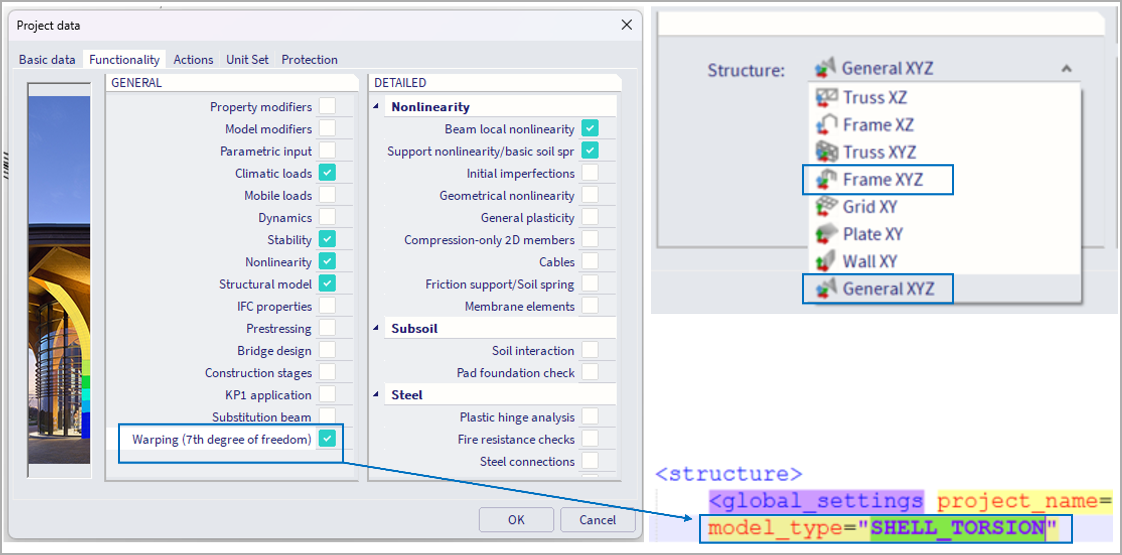
This functionality is supported only for 3D project environment, hence structure type "General XYZ" and "Frame XYZ".
If the corresponding check box in the "functionality" tab within the "project data" is activated, the 7th DoF will be considered for the current project. Internally this means, the model type will be set to "SHELL_TORSION", instead of "SHELL" (which is normally considered for 3D environments).
Further requirements
Mesh size
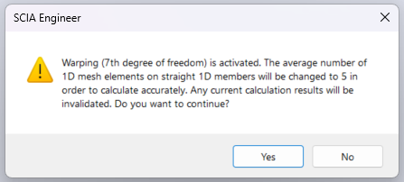
In order to make this functionality to work properly, finer mesh needs to be used for 1D elements. E.g. not 1 finite element per member, but 5 are quite sufficient. Therefore, if the "average number of 1D mesh elements" within the "mesh settings" is not set accordingly, a warning is issued informing about this after the analysis initiation, and this property is set to 5. In case finer mesh is used for 1D members, results will be more precise (e.g. up to 20, finer might result in slowing down the analysis, not improving precision significantly).
Warping and "Neglect shear center eccentricity"
In the "advanced solver settings" there is a property "neglect shear center eccentricity". This is in general not recommended to use along with consideration of the 7th DoF, and if used, there will be a warning before the calculation informing the user about this.
Activating the 7DoF for selected cross-sections
Once the functionality is activated in the project, it still needs to be turned on for selected 1D beams. This is handled by activating the property for the corresponding cross-sections which are assigned to these 1D beam elements.
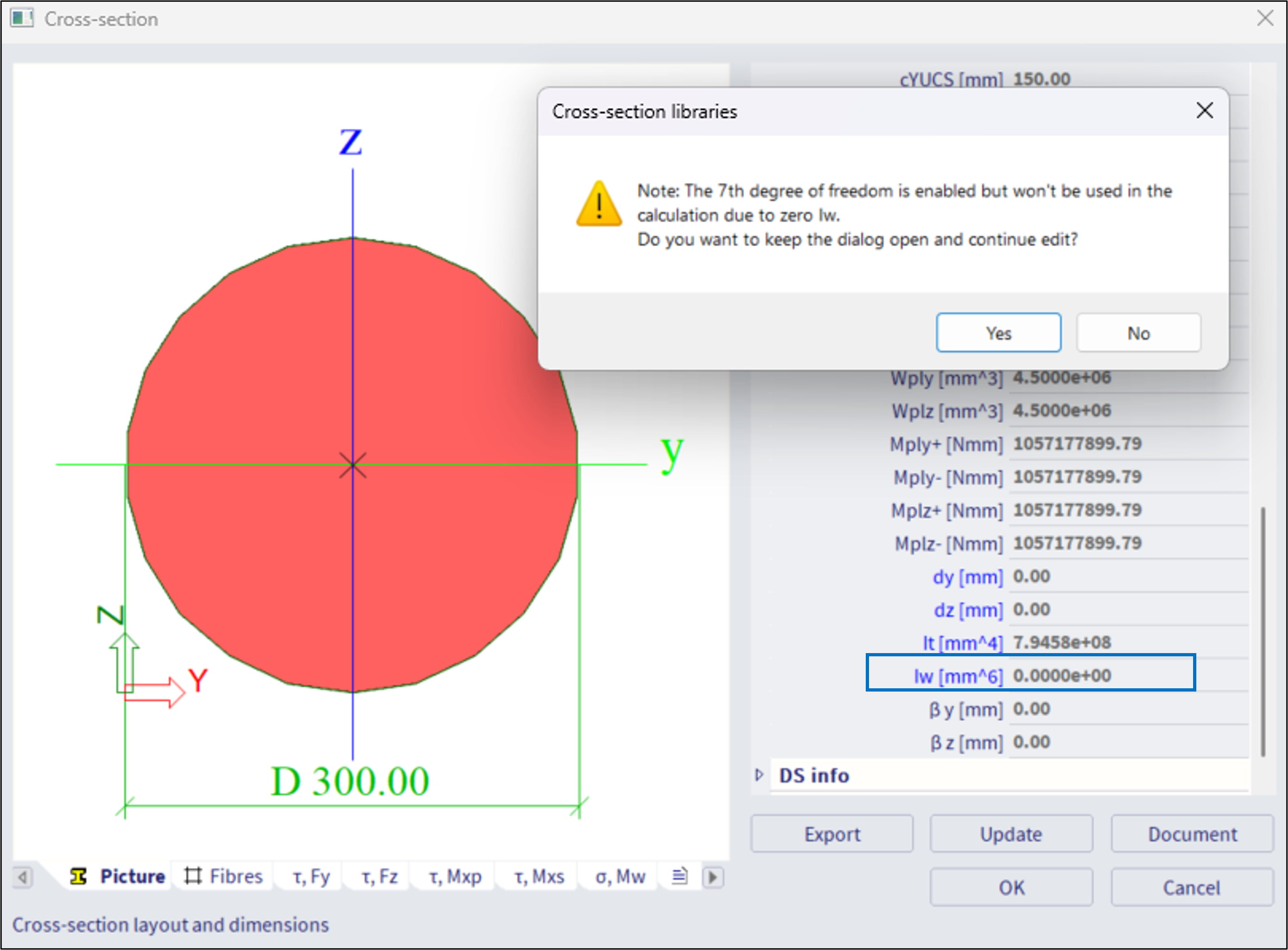
In general, the 7th DoF might be considered for any type of cross-section (of any material), also thick-walled sections, e.g. rectangular cross-section, etc. For some sections like CHS, or full circular sections (see figure below), where the warping constant I_w is exactly 0.0 m^6,, there will be a warning informing the user that 7DoF will not be used for these sections, if the warping is activated for such sections. The user will encounter such warning while closing the "cross section" dialogue.
Thin walled cross sections
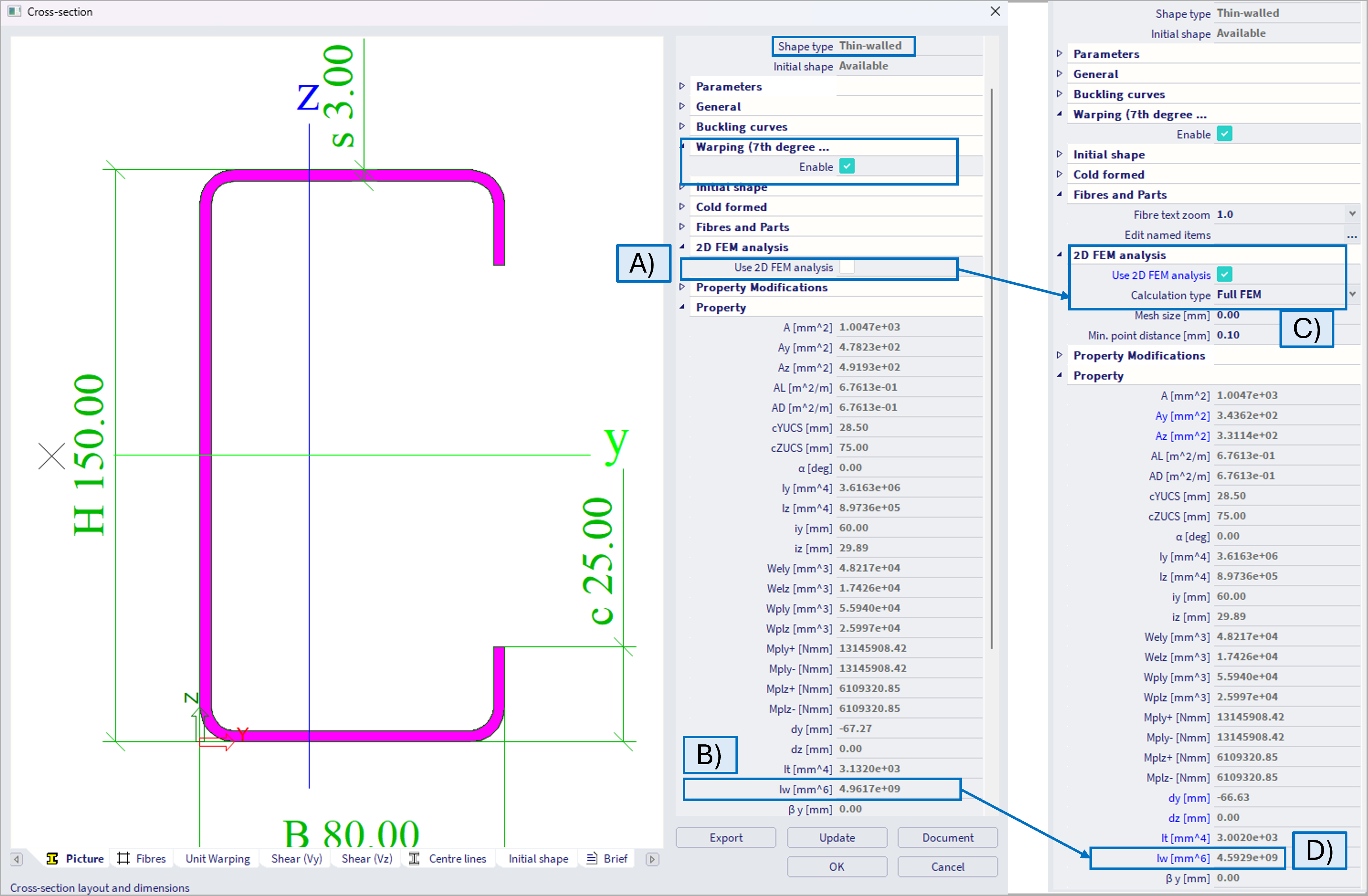
It is necessary to enable the Warping, but "2D FEM analysis" along with "Full FEM" method does not have to be activated (figure below - A), as the warping constant Iw is available (figure below - B). When the 2D FEM method to evaluate cross-sectional properties is selected (figure below - C), with Full FEM method which is recommended rather than Grashof-Jouravski method, the value of the warping constant might be slightly different (figure below - D). The difference is caused by a different approach of cross-sectional properties evaluation, and usually is not expected to be significant. In general, for thin-walled cross sections, where the cross-sectional properties are well tabulated and known, it is not necessary to consider 2D FEM method, which might in general longer the calculation.
Thick walled cross sections (and other types)
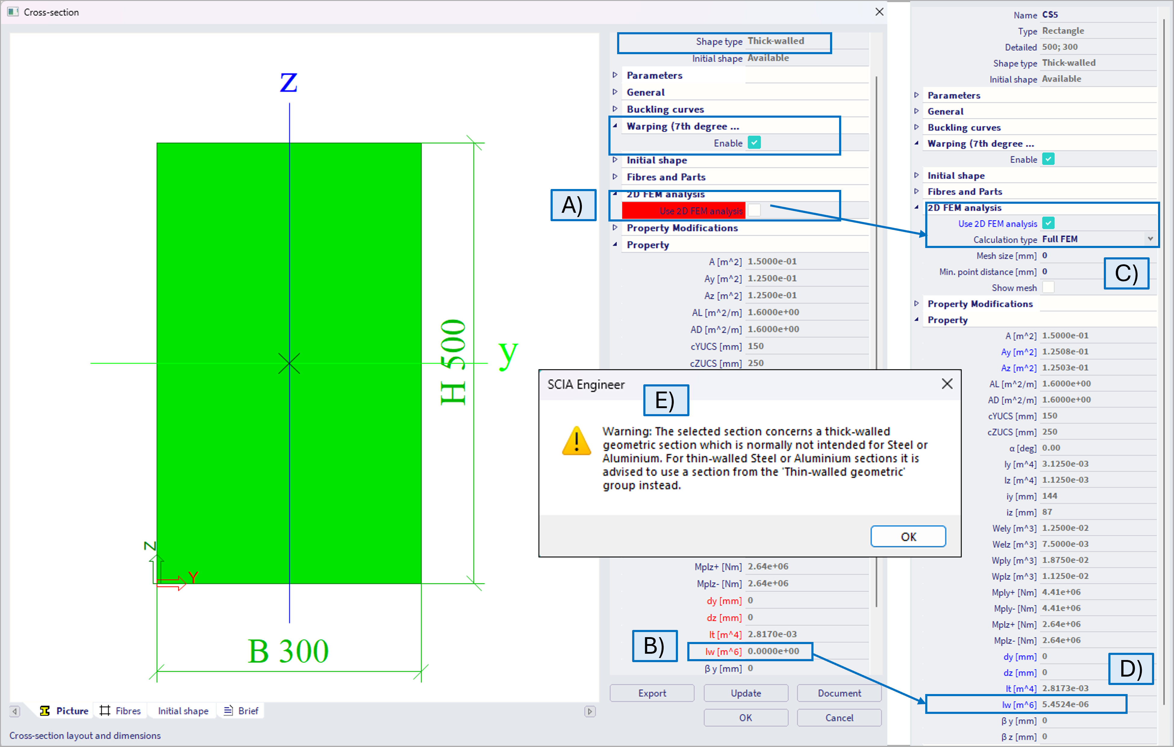
For thick-walled cross-sections, or in general cross-sections, where the warping constant Iw is highlighted by red color and equal to 0 when the 2D FEM method is not used (see figure below - A,B), it is necessary to consider 2D FEM method, ideally along with Full FEM method in order to consider the warping (figure below - C,D). In this case, the warping constant will not be 0 (unless valid 0 values for e.g circular sections, where warping does not occur). In case thick walled are used with steel material, there will be informative warning (E), as in general this is not typical use case, as in case of e.g. wood.
Further components
In order to model the interaction between several beams, and to consider the constraints of the 7DoF in some support, these entities needs to be modified accordingly. Closer information are in the corresponding chapters:
- "7th DoF (warping) - hinges".
- "7th DoF (warping) - nodal supports".
- "7th DoF (warping) - results".
7th DoF and other analyses
The feature of the 7th DoF (if turned on) is considered in all the analyses types. Below is example.
Linear stability analysis - example
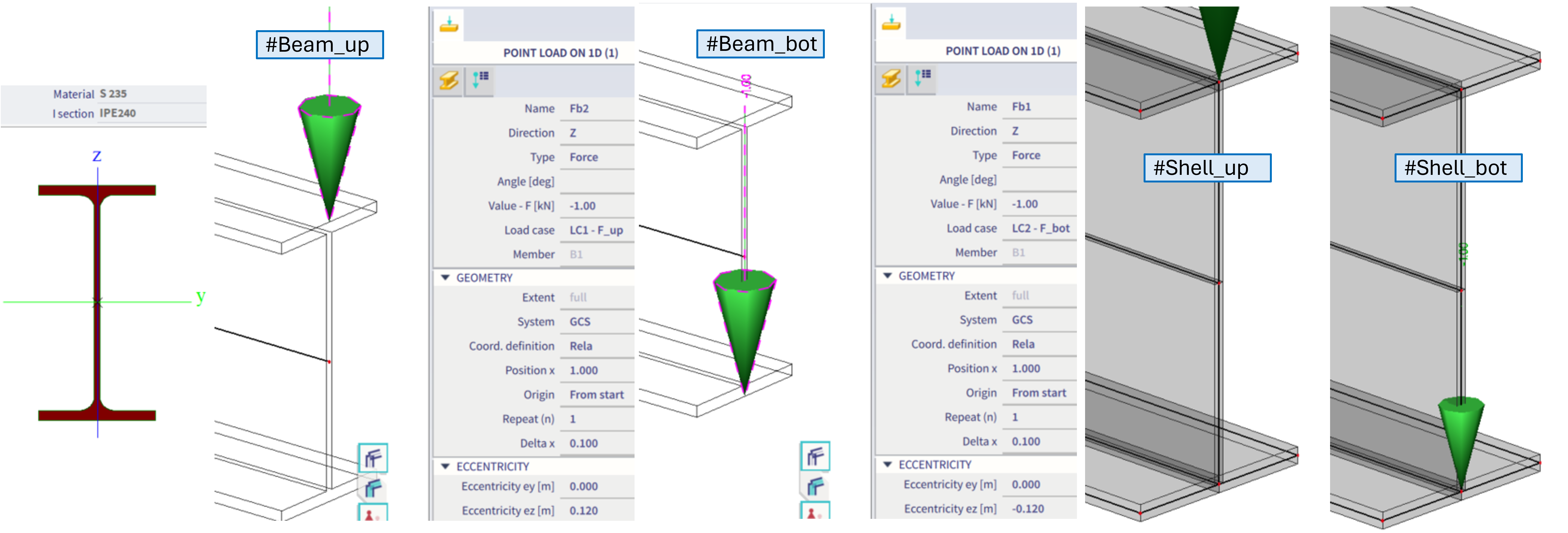
Example of a cantilever IPE240 profile, loaded by a 1kN force at the free end. The ez eccentricity is modified, so once the force is applied on the upper flange, and the other time at the bottom flange, hence introducing destabilizing and stabilizing effects respectively. Beam and shell models are compared below:
#Beam_up = beam model, 7th DoF activated for IPE240, warping constrained at the fixed end of cantilever, force applied at the upper flange at free end
#Beam_bot = beam model, 7th DoF activated for IPE240, warping constrained at the fixed end of cantilever, force applied at the bottom flange at free end
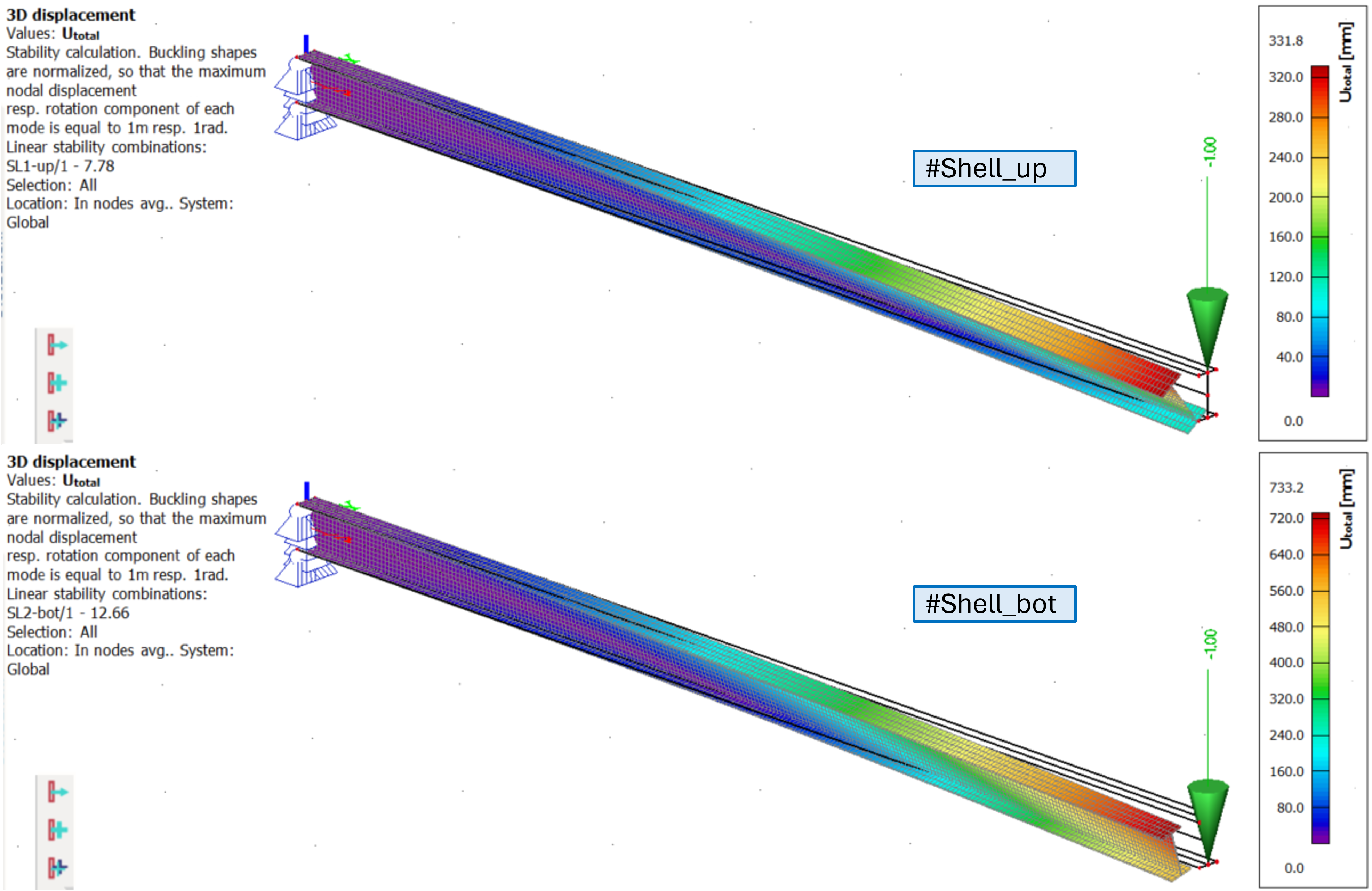
#Shell_up = shell model of IPE240, warping constrained by line translational supports along web and both flanges at the fixed end of cantilever, force applied at the upper flange at free end
#Shell_bot = shell model of IPE240, warping constrained by line translational supports along web and both flanges at the fixed end of cantilever, force applied at the bottom flange at free end
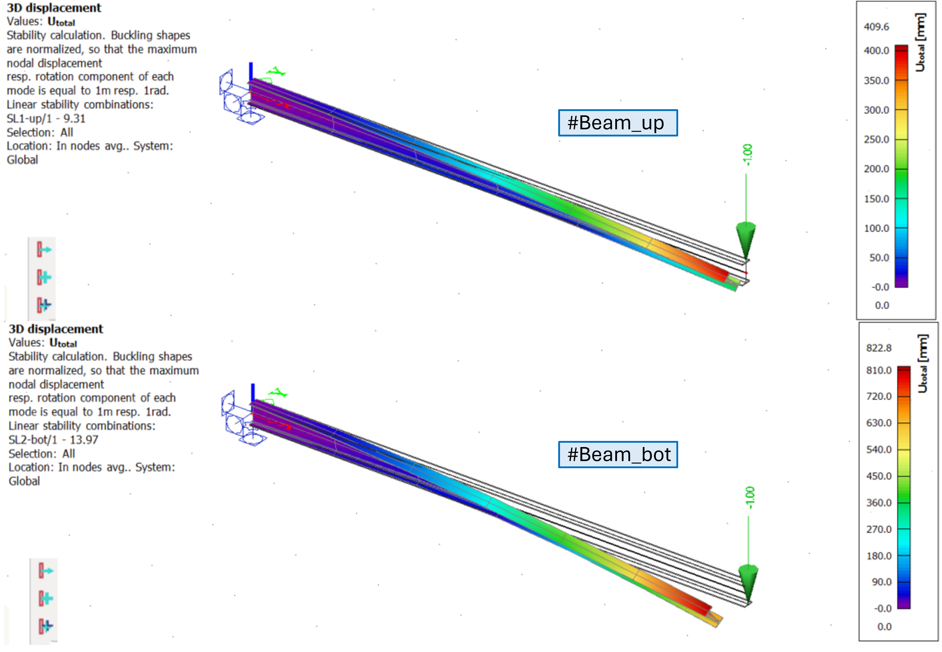
The results of linear stability of the beam variant:
It can be observed the critical coefficient in #Beam_up is smaller then in #Beam_bot, what is achieved only if 7th DoF is considered.
The results of linear stability of the shell variant:
It can be observed the critical coefficient in #Shell_up is smaller then in #Shell_bot. The values itself are slightly different from the beam model, mainly due to little difference in IPE240 section geometry (shell model neglects the extra rounded areas where flanges are connected to the web, hence, hence there is a bit larger cross-section area for the beam model)