![]()
|
||
|
|
||
As was mentioned above, there exists general concept of “strut-and-tie” model for the prediction of shear and torsional effects in concrete. The procedure for design shear reinforcement for interaction shear and torsion can be represented by diagram below:
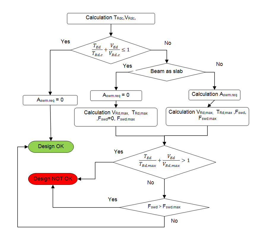
Only minimum reinforcement is required (see provided that the following condition (equation 6.31 in EN 1992-1-1) is satisfied
TEd / TRd,c + VEd / VRd,c ≤ 1
The maximum resistance of a member subjected to torsion and shear is limited by the capacity of the concrete struts. In order not to exceed this resistance the following condition (equation 6.29 in EN 1992-1-1) should be satisfied
TEd / TRd,max + VEd / VRd,max ≤ 1
Statically required cross-sectional area of the shear reinforcement per meter is calculated according to formulas
Aswm1,req = Asw,req / sl,req = VEd / (z ∙ fywd ∙(cot θ + cot α) ∙ sin α)
Aswm2,req = Aswt,req / sl,req = [|TEd| / (2 ∙ Ak) + VEd / (ns ∙ z)] / (fywd ∙ cot θ)
Aswm,req = max(Aswm1,req, Aswm2,req)
The force in shear reinforcement caused by shear and torsion effect can be calculated according to formula
Fswd = [|TEd| / (2 ∙ Ak) + VEd / (ns ∙ z)] ∙ (st / cot θ)
The maximum force which, can be carried by shear reinforcement is give by formula
Fswd,max = Aswt / fywd
where
| TEd |
torsional moment |
| TRd,c | the design value of torsional cracking moment, see "Design shear reinforcement for torsion" |
| VEd |
resultant of shear force VEd = √(VEd,y2 + VEd,z2) |
| VEd,y(z) | shear force in direction of y(z) axis of LCS |
| VRd,c | the design shear resistance of the member without shear reinforcement, see "Design of shear reinforcement for shear forces" |
| TRd,max | Maximum of torsional resistance moment, see "Design shear reinforcement for torsion" |
| VRd,max | the design value of the maximum shear force which can be sustained by the member, limited by crushing of the compression struts, see "Design of shear reinforcement for shear forces" |
| Ak |
the area enclosed by the centre-lines of the thin-walled closed cross-section, including inner hollow areas, see "Calculation of basic characteristics" |
| z | inner lever arm of cross-section recalculated to direction of shear forces resultant, see "Inner lever arm for shear check" |
| θ | Angle between concrete compression strut and beam axis perpendicular to the shear force, see "Angle between concrete compression strut and beam axis" |
| Aswm.req | Statically required cross-sectional area of the shear reinforcement per meter |
| Asw |
the cross-sectional area of the shear reinforcement calculated from inputted parameters in design default, see "Design Defaults" Asw = ns ∙0,25 ∙ π ∙ dss2 |
| Aswt |
the cross-sectional area of the shear reinforcement calculated from inputted parameters in design default, see "Design Defaults" Asw = 0,25 ∙ π ∙ dss2 |
| dss | diameter of stirrups loaded from Concrete setting or Concrete data, see "Design defaults" |
| ns | number of cuts (shear links) loaded from Concrete setting or Concrete data, see "Design defaults" |
| sl.req |
the spacing of the stirrups in longitudinal direction, if Aswm2,req > Aswm1,req: sl,req = Aswt / Aswm,req otherwise: sl,req = Asw / Aswm,req |
| fywd |
the design yield strength of the shear reinforcement. |