Moving loads generator 2D
Applicable to load 2D members.
Icon of the command:

Setting the configurations of the moving loads on 2D members via the generator
Upon opening of the "Moving load generator 2D" dialogue, the default window is depicted in the figure below. Parts #A - #I are further explained. The overall logic is actually analogical to the Moving loads generator 1D. The behaviour is practically the same, just referring to and using corresponding 2D features and library entities except of 1D.
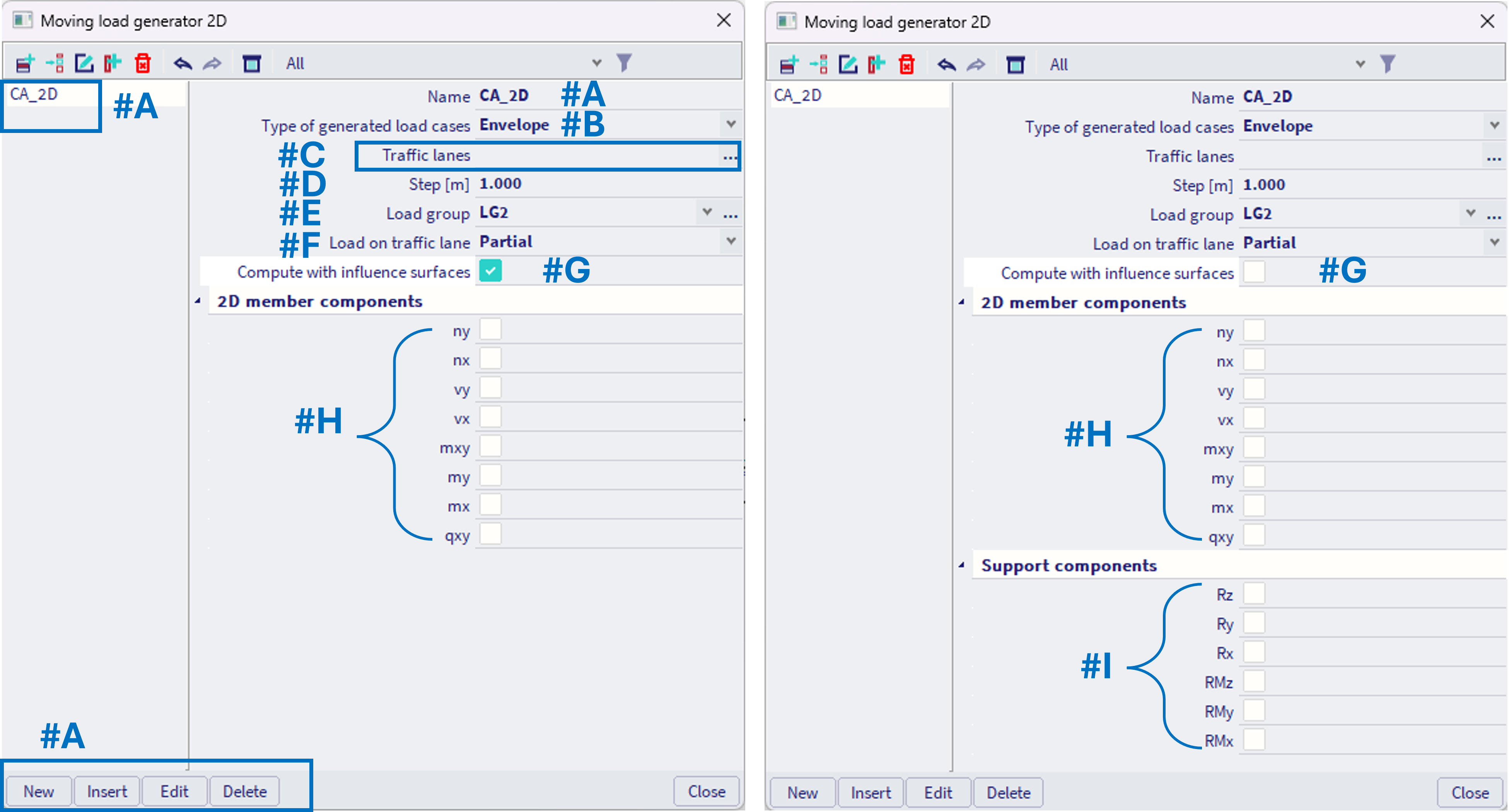
#A - The moving load generator 2D is actually a library of "CA_2D" entities (combination assembly for 2D solution). The dialogue behaves as dialogue of standard load case (or Moving loads generator 1D), it is possible to add, delete, edit "CA_2D" entities similarly to load cases. Each new "CA_2D" is by default named CA_2D1, CA_2D2,... In general, user might define several CA_2D entities (the number is not limited). However, keep in mind, that these CA_2D usually are much more demanding on calculation than standard linear load cases. Depending on the setting, one CA_2D entity might internally require several 1000 (or even more) linear load cases to be analysed by the FEM solver in the background. Everything depends on setting of the corresponding CA_2D.
#B Two main approaches are available, based on the setting "Type of generated load cases", the approach might be "Envelope" or "Influence surfaces". The options of further settings are different for both approaches. In general the "Envelope" uses brute force to determine the envelop of the extreme result values - internally, vast number of load cases are calculated, each with slightly different position of the load, and the results of these load cases are internally processed into envelope. In case of Influence surfaces, user needs to determine in which position (section) of the 2D member he is interested in extreme values of specific internal force (this requires more user control, but is less calculation demanding). It works analogically to the 1D solution of the Influence lines.
Type of generated load cases = Envelope
#B - If set "Type of generated load cases" = Envelope, this means, internally several linear load cases will be analysed, respecting varying positions of the load sets within the load systems, possibly assigned to several traffic lanes. This might lead to vast numbers of internally analysed load cases. Out of this vast number of load cases, a resulting envelope will be provided (hence the name "envelope"). For this option, it is also required to define, which internal forces, #H, and / or which support reactions, #I, user wants to investigate through the whole structure. At least one component out of the options in #H,#I needs to be selected.
However, differently from the Moving loads generator 1D, where also the envelope results for "CA" entities were present, there is no direct result for the envelope entities "CA_2D". The reason is, for 2D results the envelope is not feasible to be plotted graphically (e.g. envelope of 2D internal forces my plotted graphically on 2D members).
In order to process these results further and combine with the results of another load cases (self weight, permanent loads etc.), for each CA_2D entity, 2n result load cases will be provided within the results of the load cases. 2 stands for the maximum and minimum, and the nstands for number of selected items (internal forces, reactions) from available options in #H,#I (1 ≤ n ≤ 14). These 2 load cases are envelope results of the maximum and minimum effects of the selected entity (#H,#I), where for each section, the corresponding values of the remaining (non selected in #H or #I) results (either internal forces or reactions) are provided (in order to combine correctly). See also example below:
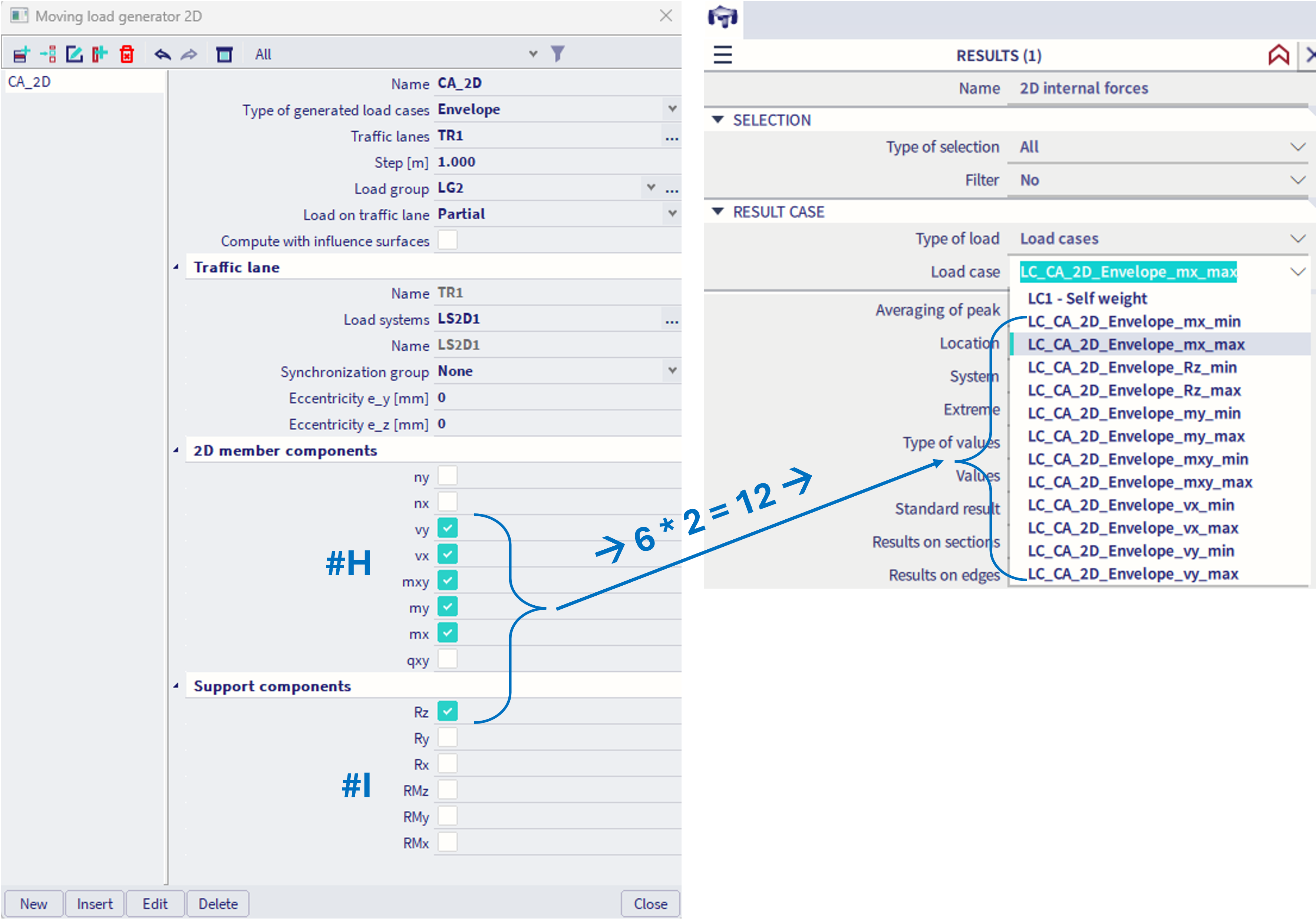
For the result case, which yields 2D results, e.g. max mx, all the corresponding 2D results are provided (nx, ny,... in figure below e.g. mxy is depicted). However, there are no results of reactions present in this result case. See example below.
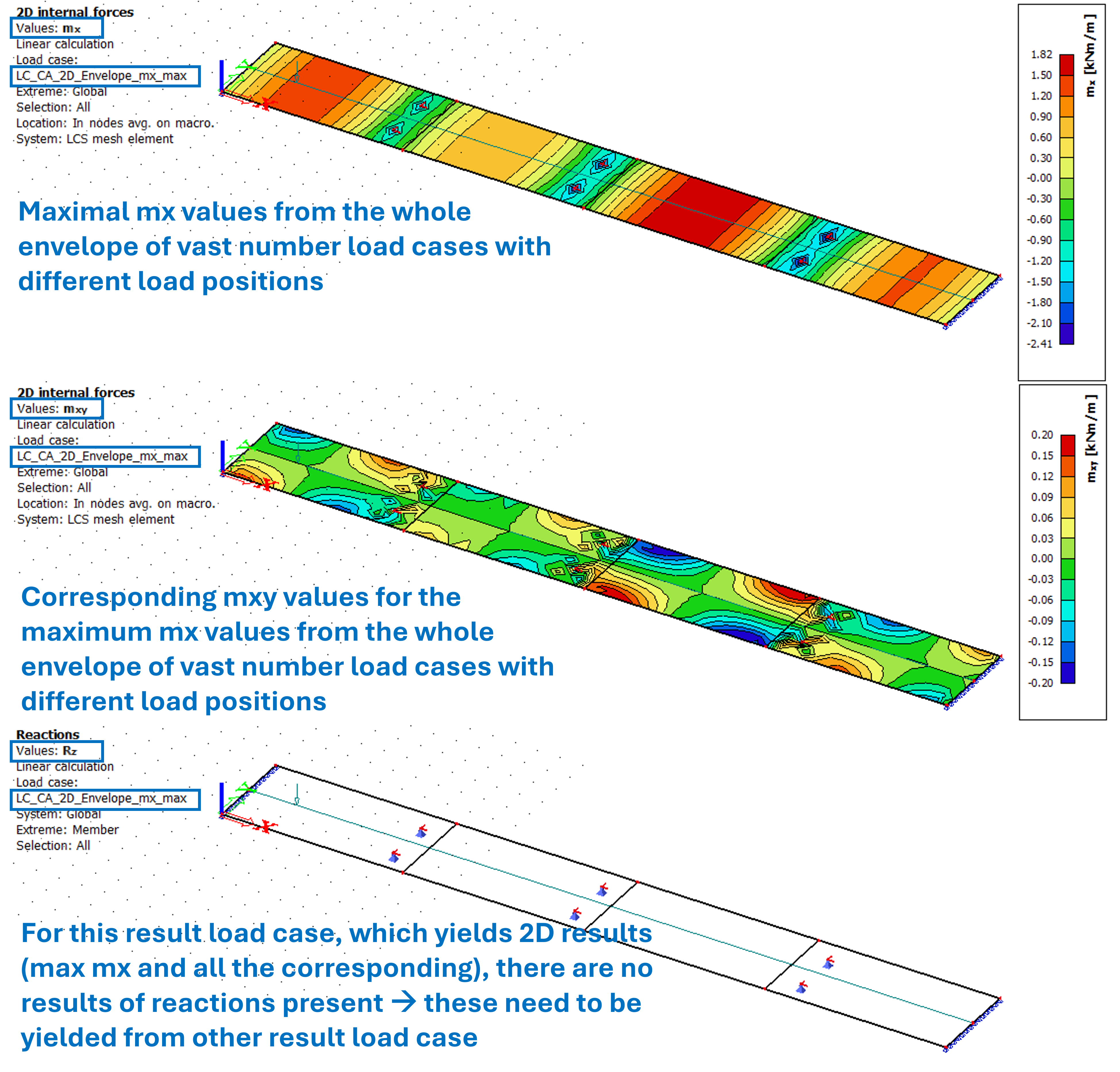
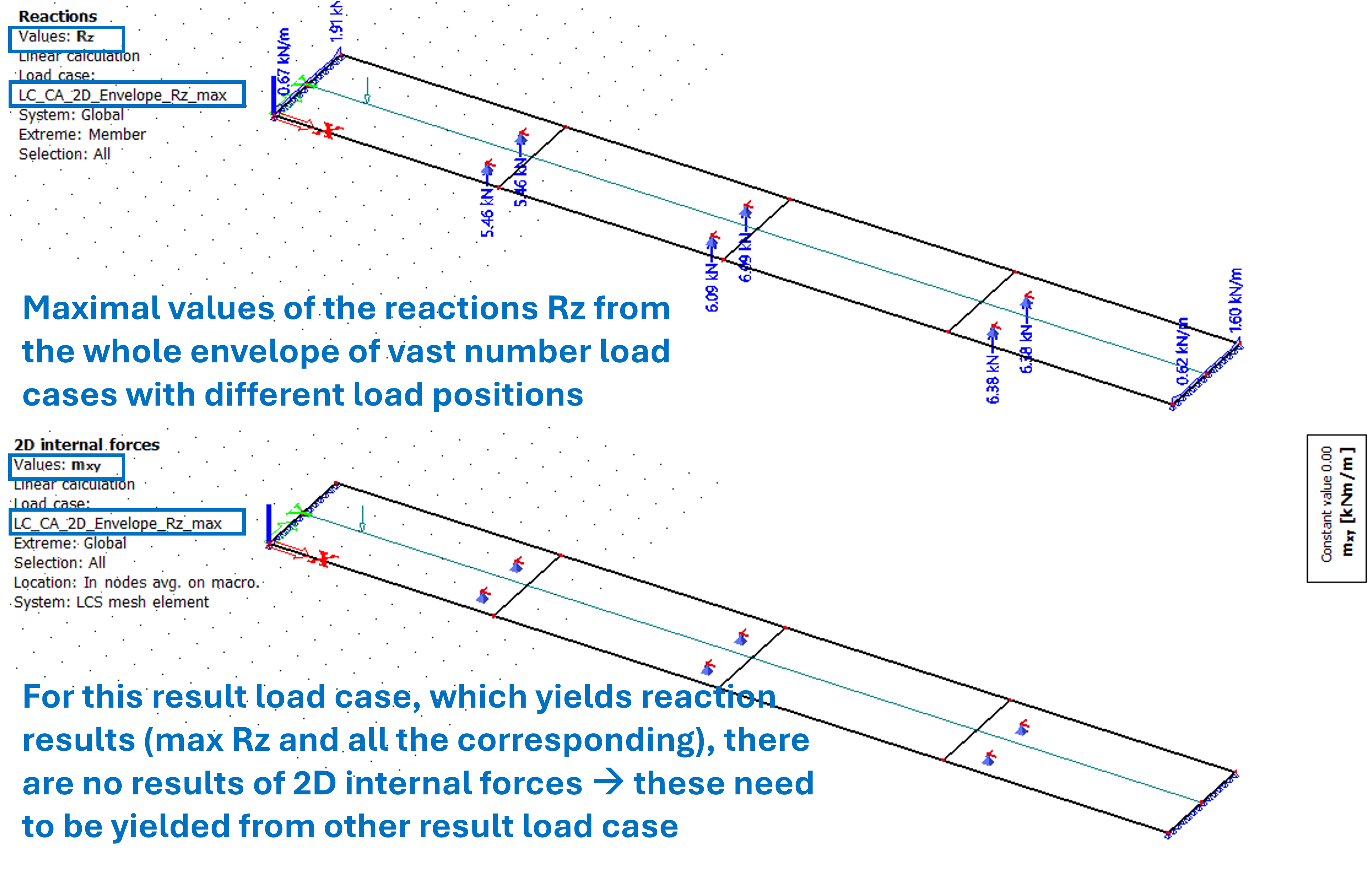
The results of reactions need to be obtained from the corresponding result load case for reactions. In this load case, all the corresponding reaction directions are present, but there are no result for 2D internal forces present. See example below. Keep this in mind when creating further combinations with the other load effects (self weight, permanent load,...). Depending on what is to be checked, the corresponding result load cases should be included in the combination.
#C - Assigned traffic lanes - by selecting the "..." button, it is required to assign traffic lanes to be loaded within the corresponding CA_2D entity. No traffic lane is assigned by default. For each selected traffic lane, separate section in the dialogue is provided (#C1, #C2). At the top of this section, it is noted for which traffic lane the following setting belong.
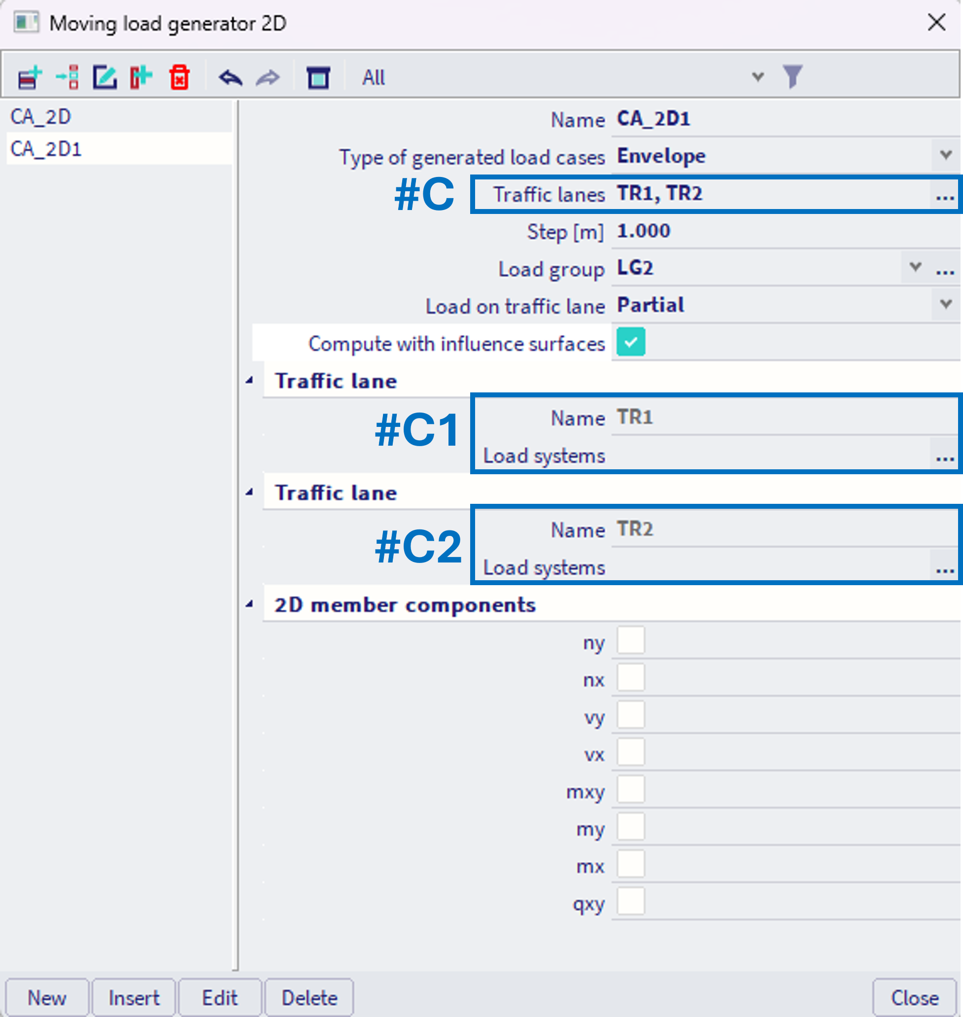
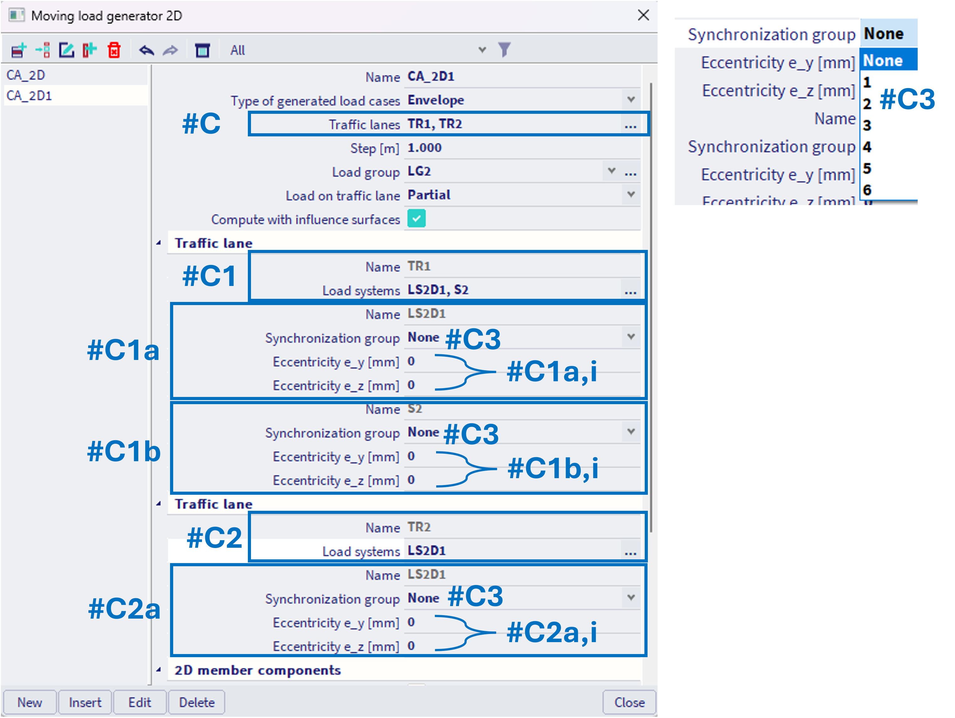
Furthermore, for each traffic lane, it is necessary to assign at least one load system. By clicking "..." within each considered traffic lane (#C1, #C2) a selection dialogue is provided, from which available load systems might be assigned to traffic lanes. One load system might be used by several different traffic lanes. Based on the number of assigned load systems, as many separate subsections of the dialogue are provided (#C1a,#C1b, #C2a). In example below, 2 load systems (named LS2D1 and S2) are assigned to traffic lane TR1, and one load system (LS2D1) is assigned to TR2, hence there are 3 separate subsections. In general, the number of subsections is not limited, but again, keep in mind that the larger the number, the more internal combinations (or in this case rather variations or permutations, as the order also plays role here) of mutual load positions exist, what might significantly increase the computational time.
Each load system within each traffic lane might act on some eccentricity e_y or e_z. E.g. even when the top of the bridge is modelled by 2D members, the trajectory of the moving load is modelled by continuous line, hence there is one referral Traffic lane 2D component in SCIA model, but there are actually multiple traffic lanes (transport terminology) on this bridge (e.g. two way road, highway,...), each such traffic lane would be considered by a uniquely assigned load system (#C1a,#C1b) within this traffic lane (#C1). For each such assigned load system, the appropriate eccentricity e_y should be defined (#C1a,i,#C1b,i), in order to consider traffic loads correctly.
Additionally, each unique assignment of a load system to traffic lane (#C1a,#C1b, #C2a) might be considered within some synchronization group (#C3). It is possible to synchronize loads not only within one traffic lane (e.g. within #C1), but also between several traffic lanes. Hence the synchronization group acts through whole the "CA_2D" entity. It is possible to set 6 different synchronization groups numbered 1-6, or "none". All the loads through one "CA_2D" entity within specific number of synchronization groups are "moving together". If "none" is set, loads within this load system within specific traffic lane are not synchronized with any other load within the corresponding "CA_2D" entity.
Overall, the assignment logic of theLoad Systems 2D to Traffic lane 2D within the moving load generator works the same way for 2D solution, as it works for 1D by Moving loads generator 1D. Examples of specific configurations for 1D solution are provided in this chapter. For moving load 2D, this works analogically.
#D - Step - in units of length - this defines the step size, which will be considered as span of the varying load positions. The finer the step, the larger number of internal load cases (each with different position of the load) need to be analysed. Set accordingly respecting the structure size (the length of traffic lane).
#E - Load group - set the load group in which the generated result load cases will be assigned.
#F - Load on traffic lane:
Complete = internally considers only such load cases of varying load positions, where all the loads are applied on the defined traffic lane. This setting should be used when modelling e.g. crane loads, as the crane wheel cannot go outside the track.
Partial = internally considers also load cases, where only part of the load is applied on the defined traffic lane. This should be used when modelling traffic loads on bridges for example, where if the train enters the bridge, just part of the train is loading the bridge (and analogically when it exit the bridge). Hence this setting results in more internally analysed load cases.
#G - Compute with influence lines - This option automatically creates vast number of calculations using influence surfaces in the background and merges the results into the envelope. In order to understand how this feature exactly works, first study how the explicitly defined influence surfaces (or lines) work in this chapter and also chapter below (what happens when within the CA_2D entity the "type of generated load cases" is set to "influence surfaces"). If this check box is activated, along the traffic lane in each position (respecting the defined step size, e.g. with 1m span), influence surface for each selected 2D internal force result(#H) will be calculated. Hence, in each position along the traffic lane, the corresponding linear load cases using the Unit deformation of 2D member will be analysed firstly (in the background). For each such influence line, two linear load cases with extreme values (min and max) for the corresponding 2D internal force will be firstly determined (to find the position of these extremes based on the influence surface) and subsequently analysed. The envelope will be provided out of the results of these internally calculated load cases. This solution offers possibility to use the reduction of the load in places when the loads acts in favourable direction (decreasing the corresponding internal force at the considered position) - hence the load multipliers for favourable and unfavourable positions defined within the Load Systems 2D are valid for the "envelope" solution only when this check box is activated (when the influence surfaces are used). This works analogically to the 1D solution. In 2D solution, the positions for which the influence surfaces are internally calculated are considered only along the trajectory of theTraffic lane 2D (which is however 1D line), not along the whole surface of 2D members this Traffic lane 2D is allocated to. In case user is interested in some extreme value of internal force on a different position then some point on the trajectory of the Traffic lane 2D, it is needed to explicitly define influence surface for this internal force for this position, hence to set the "type of generated load cases" to "influence surfaces".
Surface loads and envelope type of generated load cases for mobile loads 2D
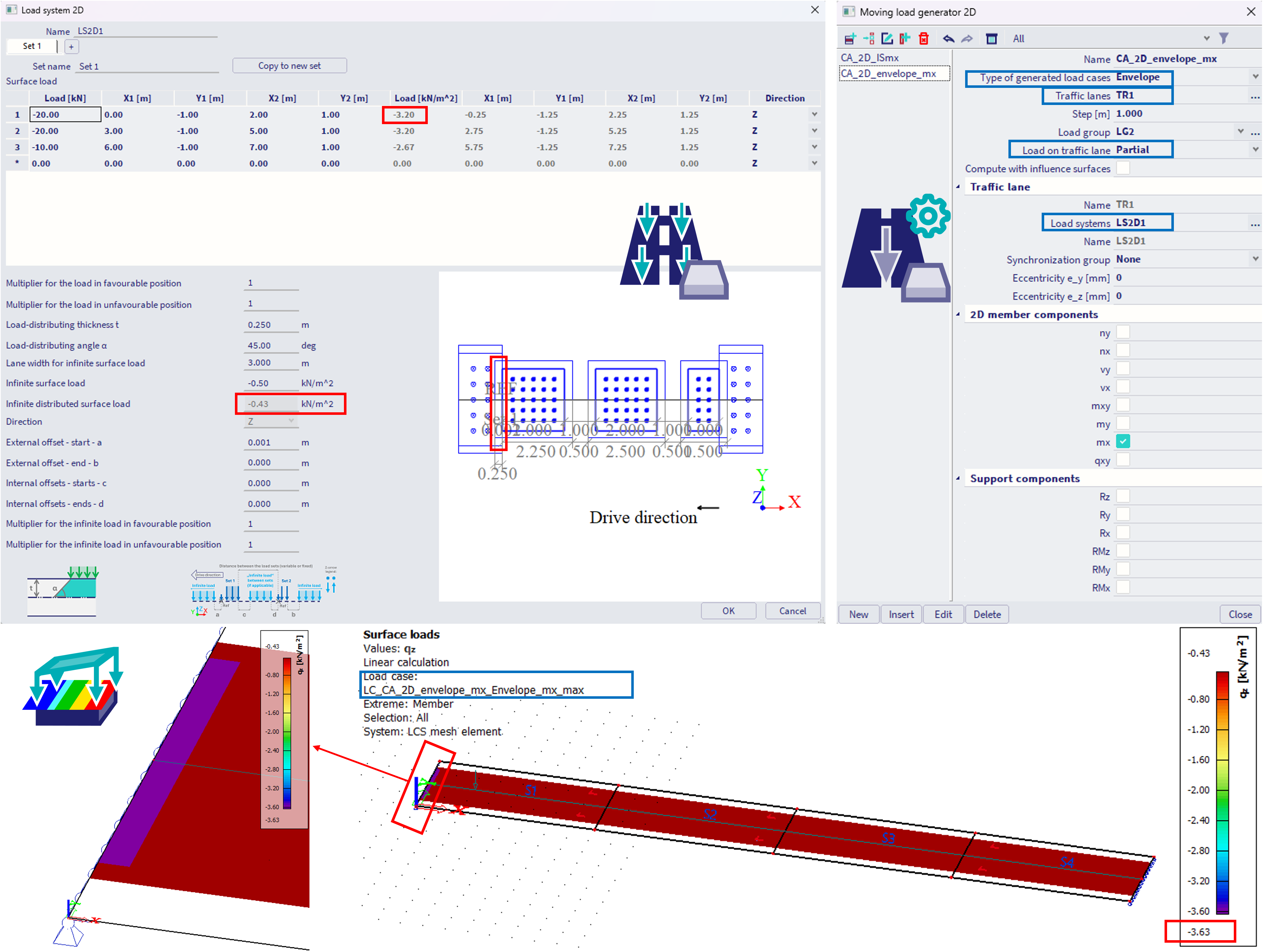
For the 2D solution, it is possible to verify the defined load in the Load Systems 2D, how it was applied on the structure, using the feature of Surface Loads (2D results).
However, for the "envelope" type of generated load cases, only the first position out of the vast number of the considered load positions is always depicted for the corresponding generated result load cases.
In the example below, with the "load on traffic lane" = "partial" within the "moving load generator", the first position is when the first load set enters the structure at the begin of the Traffic lane 2D trajectory. At this position, it might be verified that the value of the first distributed load is -3.2 kN/m^2, and it overlays with the "infinite load" which is -0.43 kN/m^2. hence these two values are summarized into -3.63 kN/m^2, what fits with the plotted result (purple values from the scale).
In order to see (to check) all the loads of the load system (if it fits within the length of the defined traffic lane), it is possible to set "load on traffic lane" = "complete" (just to check the load, as this setting would be normally applicable for crane, where only all the loads from the corresponding load set might be applied on the traffic lane).
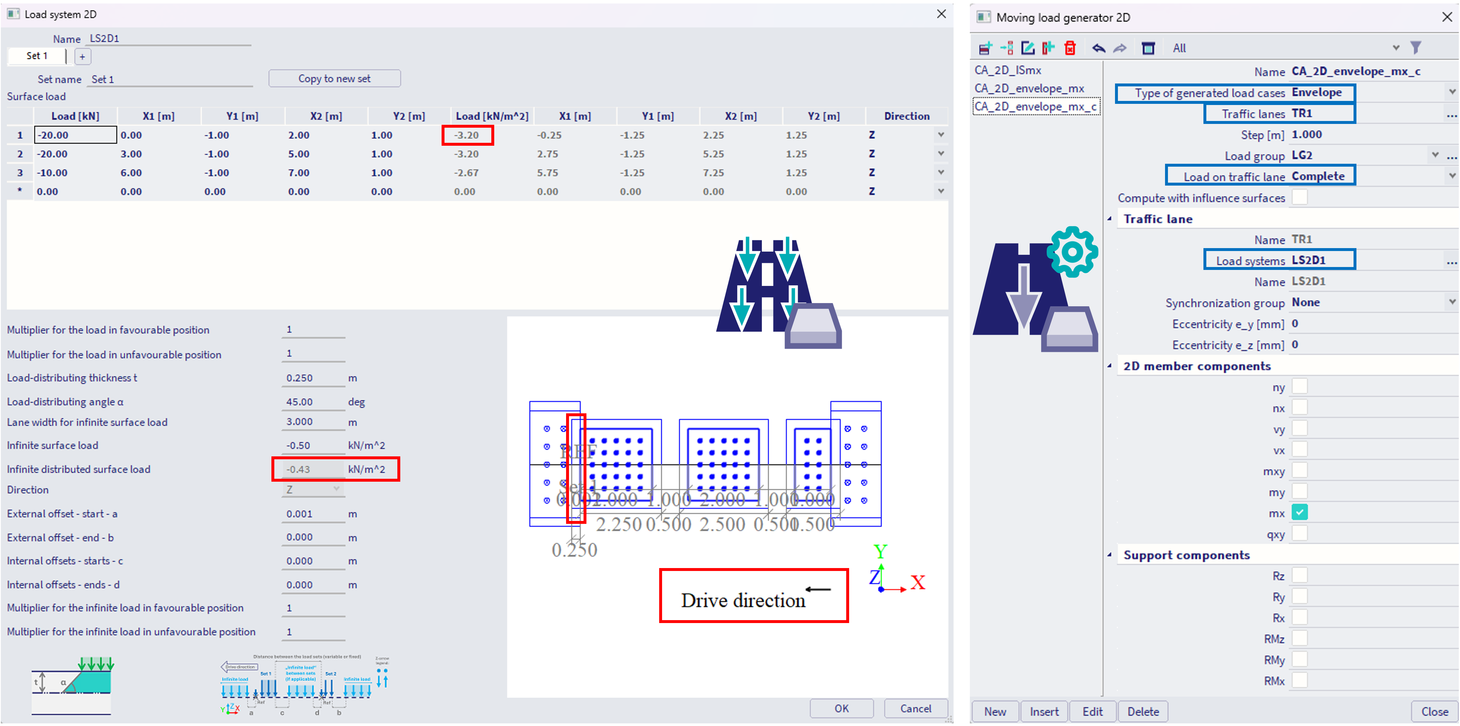
In this case ("load on traffic lane" = "complete"), it is possible to verify whole the load and also where the begin and the end of trajectory is considered - see the example below. The positions are however still just the very first positions out of numerous possible positions of the load within the traffic lane.
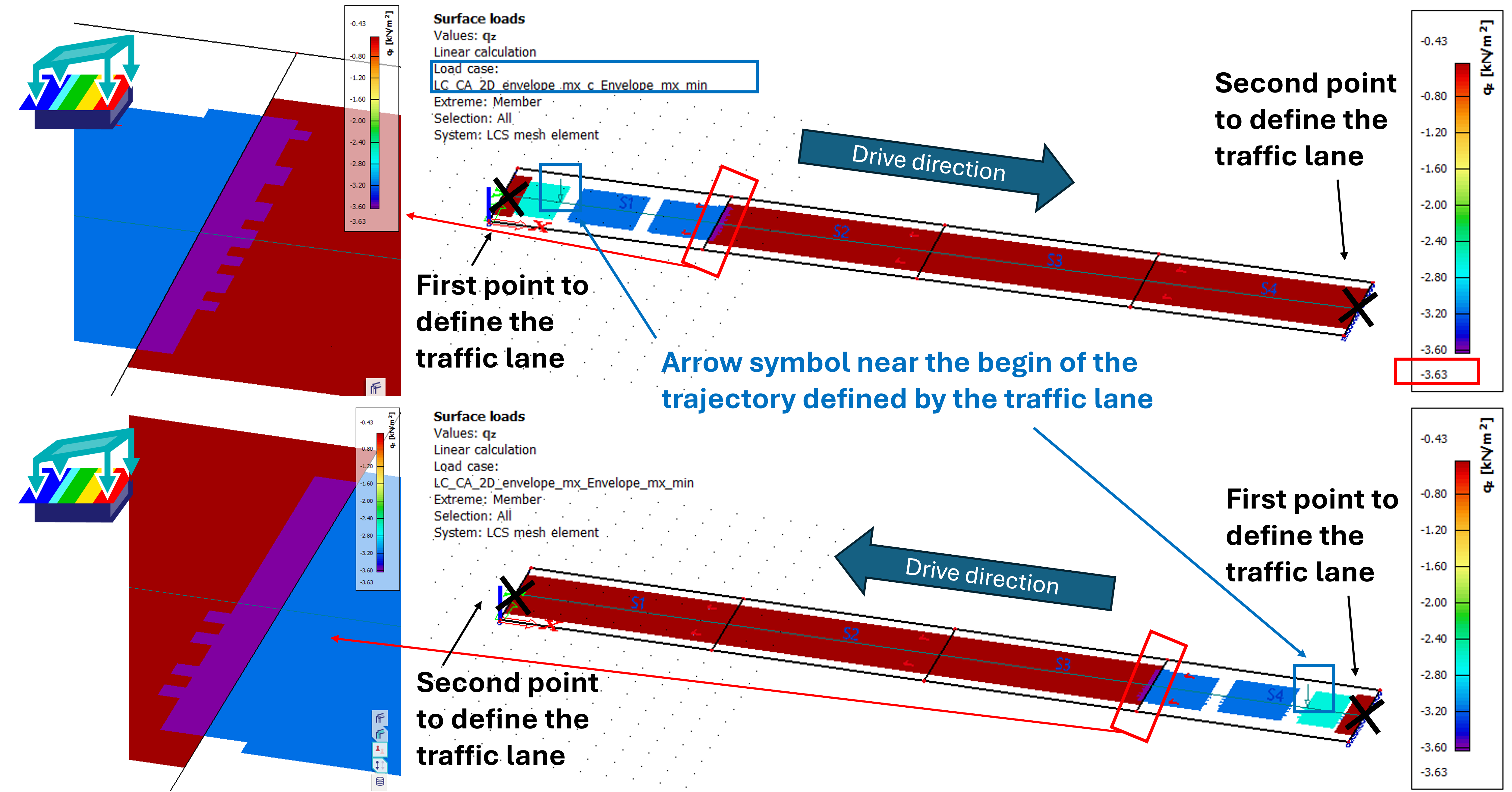
Note that the begin and the end of the trajectory are considered based on how the Traffic lane 2D was defined - what was the first point of the definition. The little arrow symbol is always positioned near the begin of the trajectory.
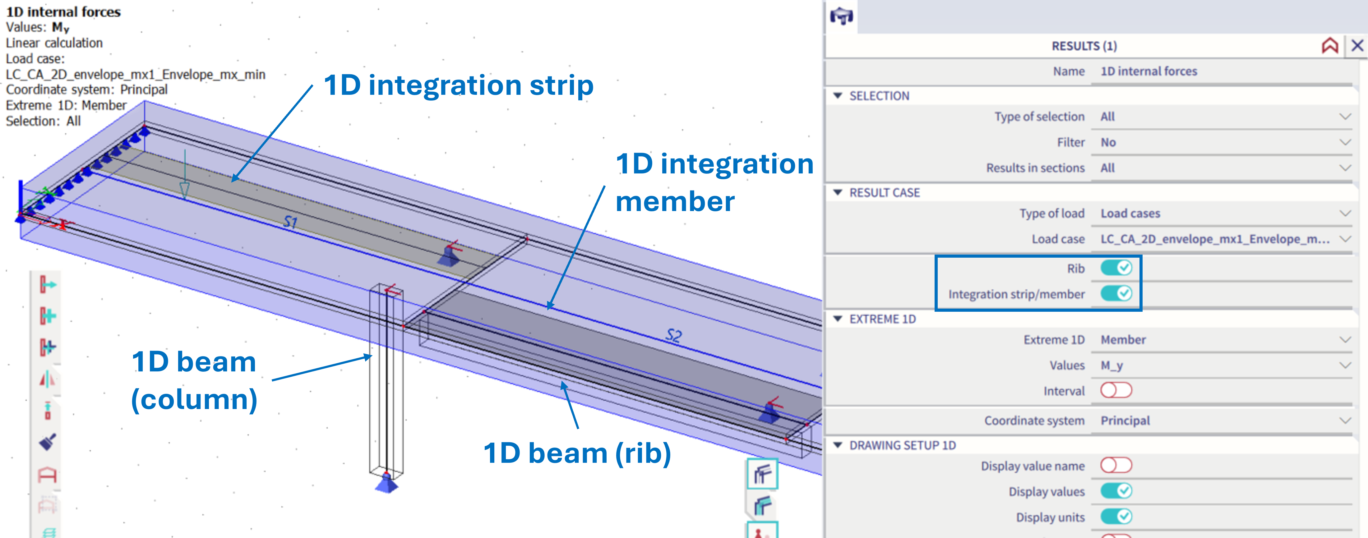
Integration members, strips and ribs and 1D results overall, along with envelope type of generated load cases for mobile loads 2D
For these generated envelope result load cases (if the "type of generated load cases" #Bis set to "envelopes", no matter whether influence surfaces are considered in the background or not #G), only 2D results are available, not any 1D results at all - e.g. direct 1D results or those integrated (rib, integration strip, integration member). Keep this in mind also when including these envelop load cases in the combinations.
The issue is, that these specialized generated result load cases for maximums / minimums for 2D magnitudes won't work for 1D elements (and vice versa), as the magnitudes there are different and cannot be mapped from 2D to 1D (and vice versa) because in the load cases we need the specific min / max magnitude and its dependent magnitudes for it to work properly in checks for example.
The envelope part in some of the results is, let's say a bonus, which gives you min / max from all the magnitudes, but not dependent magnitudes to complement it. So it's not advised to use these for checks or 1D stress calculation, for example.
Type of generated load cases = Influence surfaces
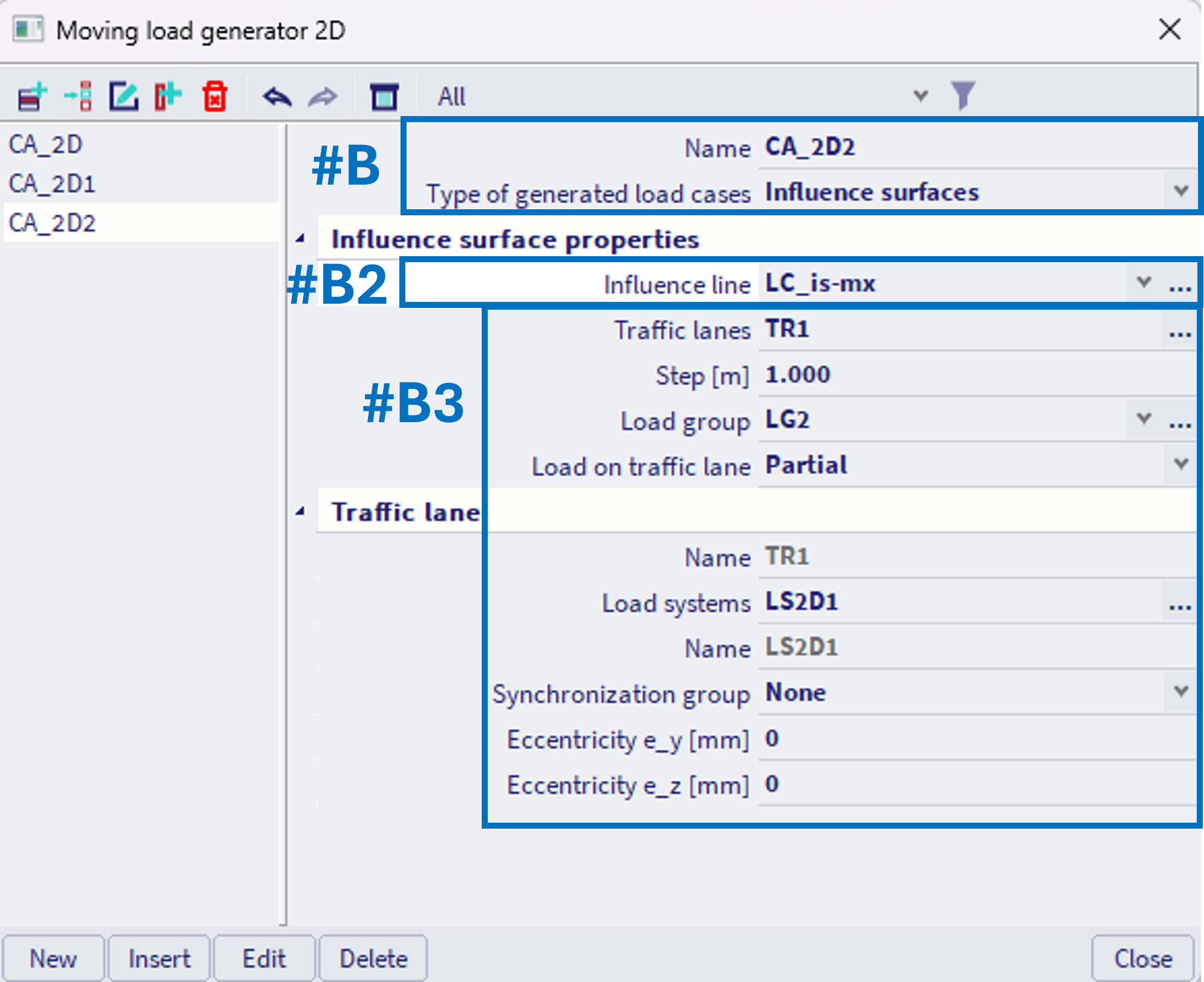
If the "type of generated load cases" #Bis set to "Influence surfaces", specific influence surface needs to be assigned to this CA_2D entity - #B2. All the other parameters, as the logic of assignment of the traffic lanes and load systems for specific traffic lanes belonging to some synchronization groups, - #B3, remains the same as in previous case (see above "type of generated load cases"="envelope").
Notes:
- the property "Compute with influence lines" is not present, as when already type of generated load cases is set to "influence lines", this setting has no additional sense.
- "Step" is still present, and now represents step size, which is considered when numerically evaluating the extreme positions of the load based on the corresponding influence line. The finer the step, the more precise is the exact position of the applied load, but the calculation might take longer of course.
The detailed work flow, of how to define and use the influence surfaces - #B2, is in this chapter.
Example - using influence surfaces
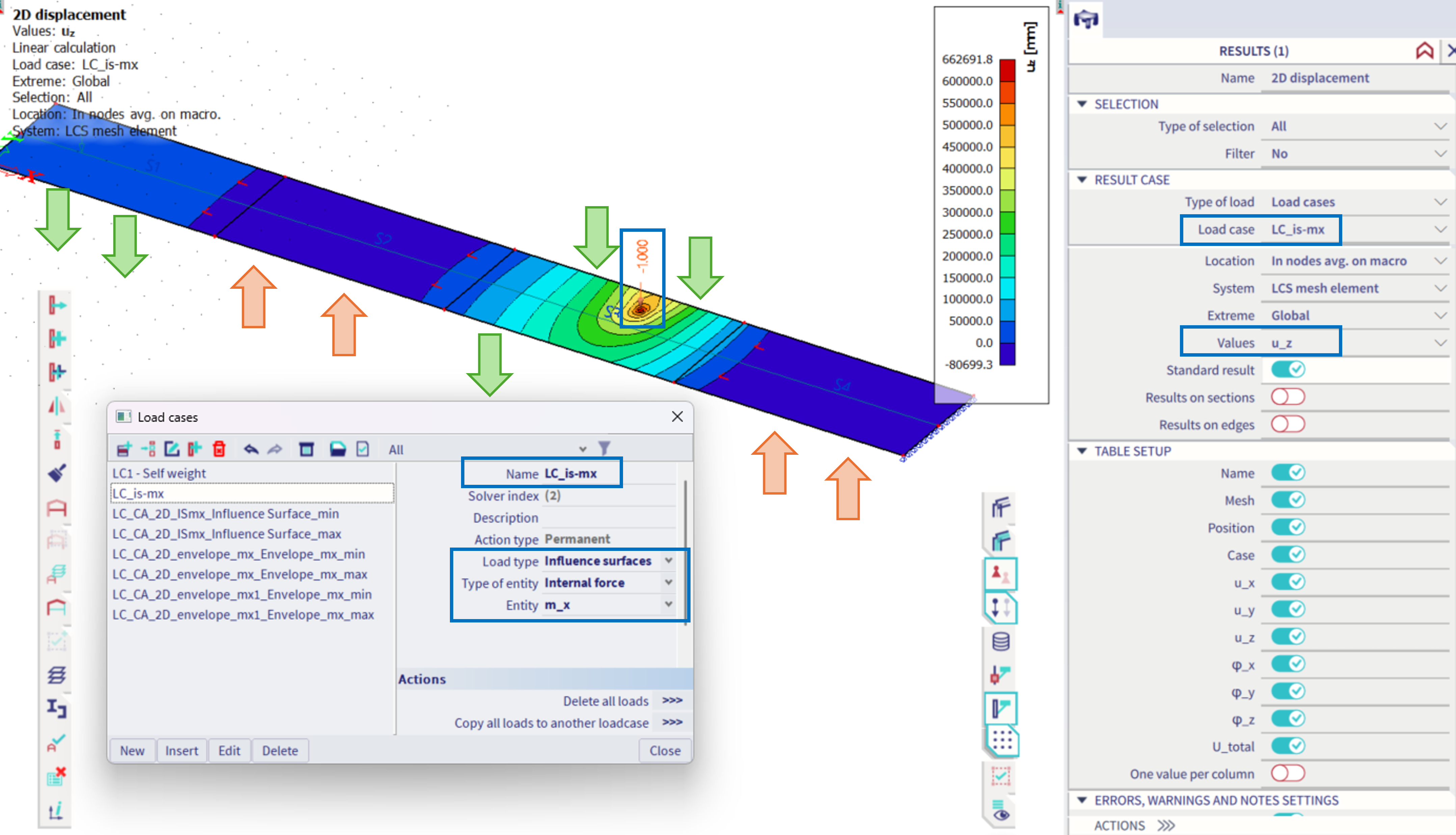
A simple load system is prepared, consisting of only one load set, and the special load case of the influence surface is assigned to the corresponding CA_2D entity:
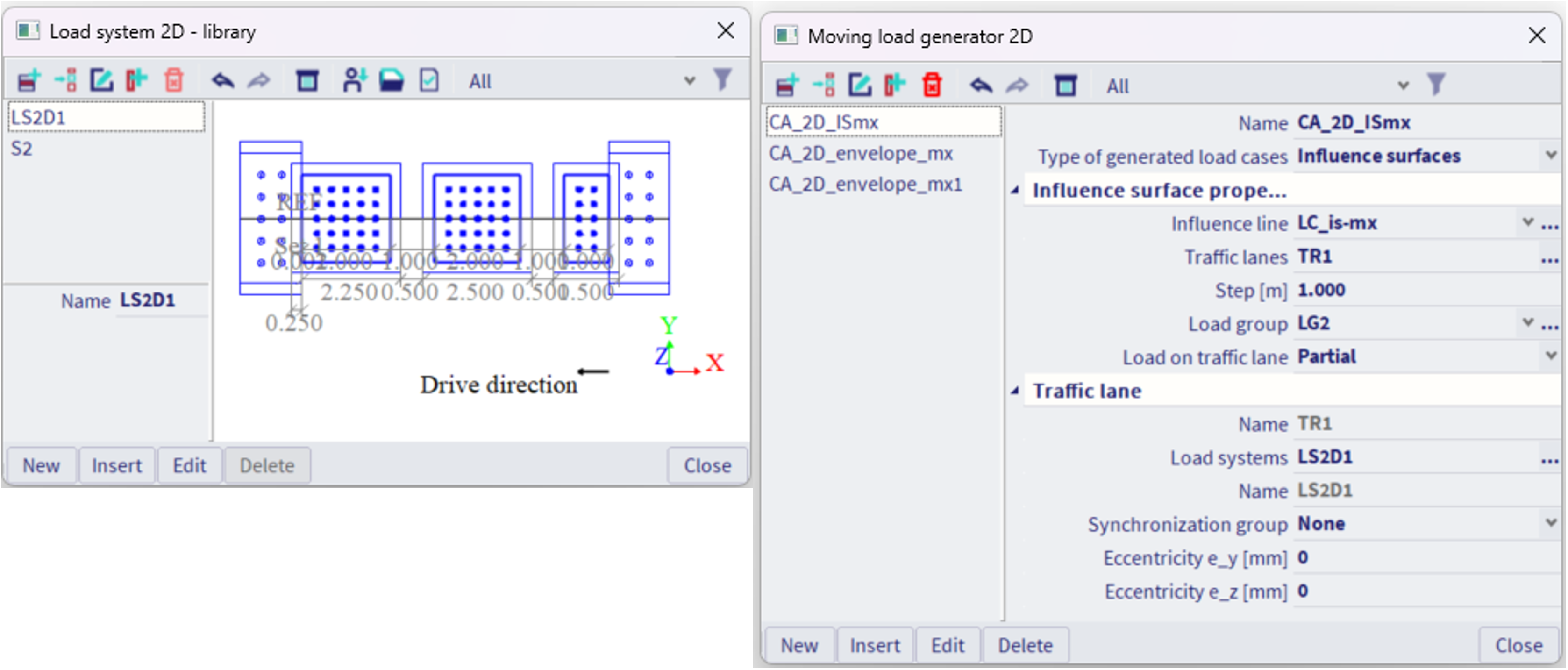
The load case of the influence surface is set to act as the influence surface of bending moment m_x, and the content of this special load case is one unit load in order to define position - see also Unit deformation of 2D member. The influence surface of m_x at this position is actually the u_z 2D displacement result of this special load case (see figure below). In order to maximize the m_x in this position, the load should be ideally applied as marked by the green and orange arrows:
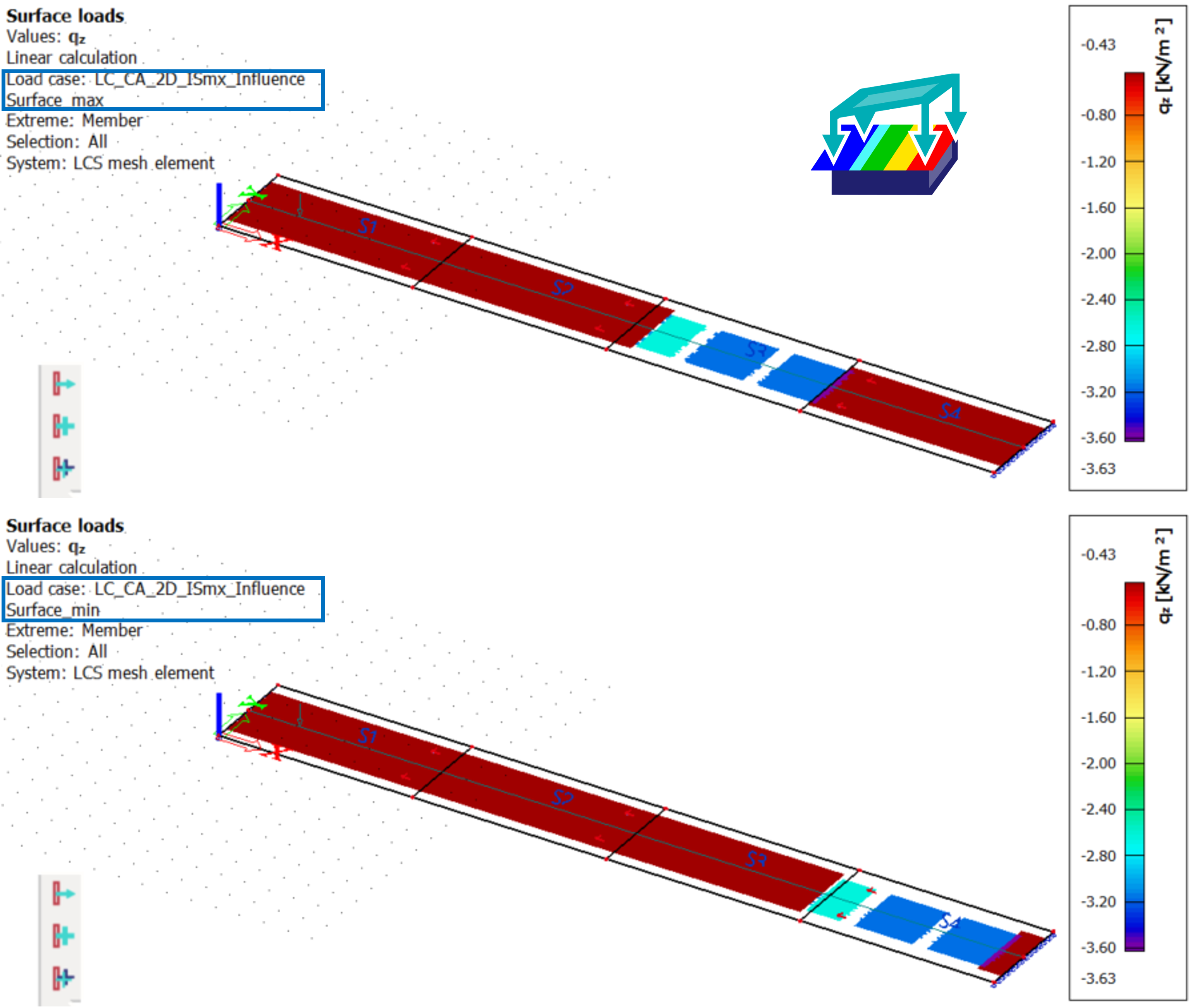
After the analysis, the two result load cases are generated - to achieve extreme values, min and max of the m_x in the defined position. It is possible to verify the position of the applied load by the Surface Loads (2D results):
In case the same load system will be used, just with altering of the "multiplier for the load in favourable position" within theLoad Systems 2D settings (e.g. setting the coefficient to 0.1), it might be verified based on the shape of the influence surface, that indeed, at the positions where the load (in this case it has effect only for the infinite load) would decrease the m_x value for the load case where maximal m_x is expected, the load is decrease to 10% of the original value - see figure below. The multipliers for standard (not infinite) load, and in unfavourable direction works analogically.
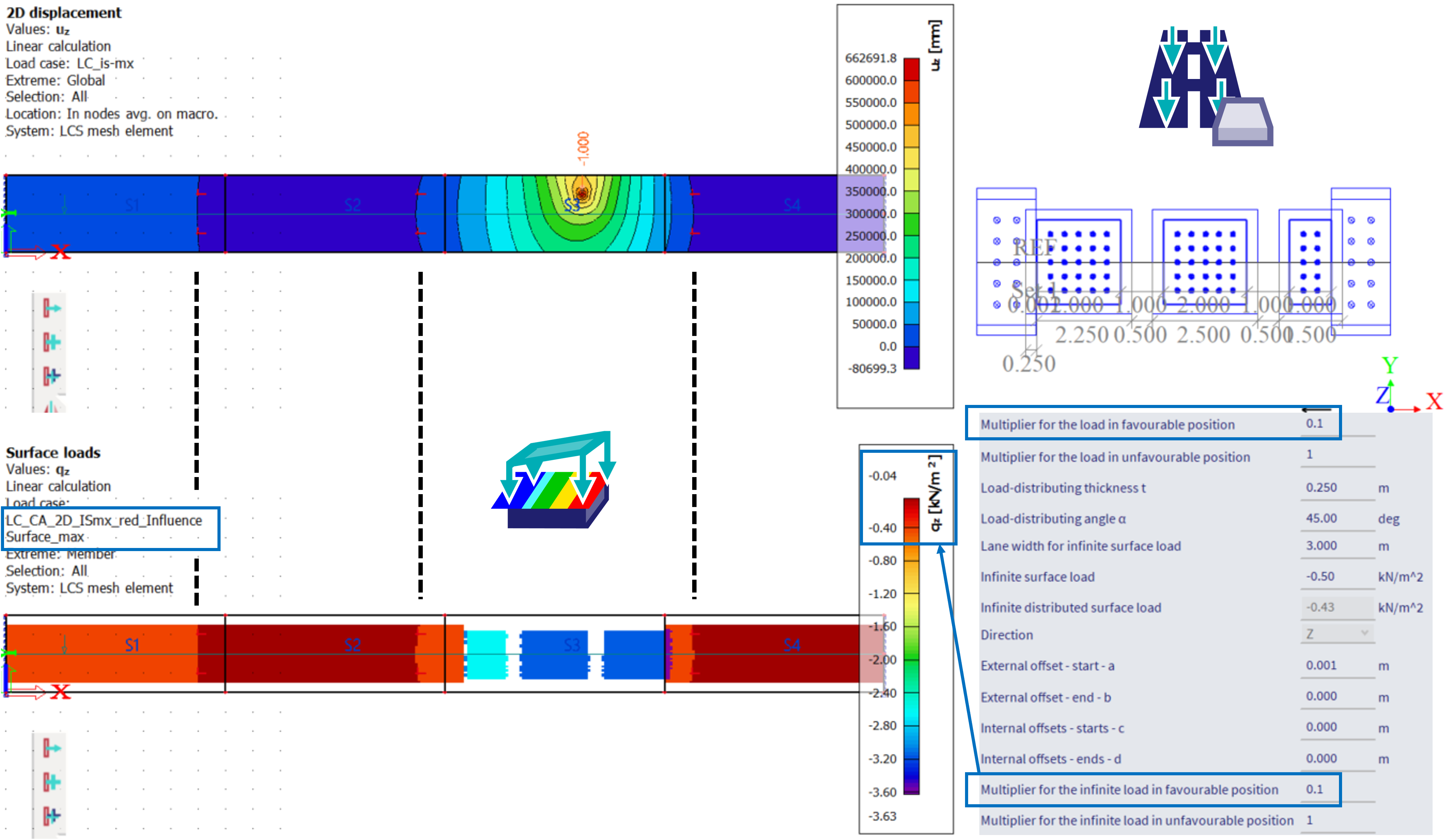
This is one of the main benefits of using the influence lines explicitly (possibility to use the multipliers for the load)
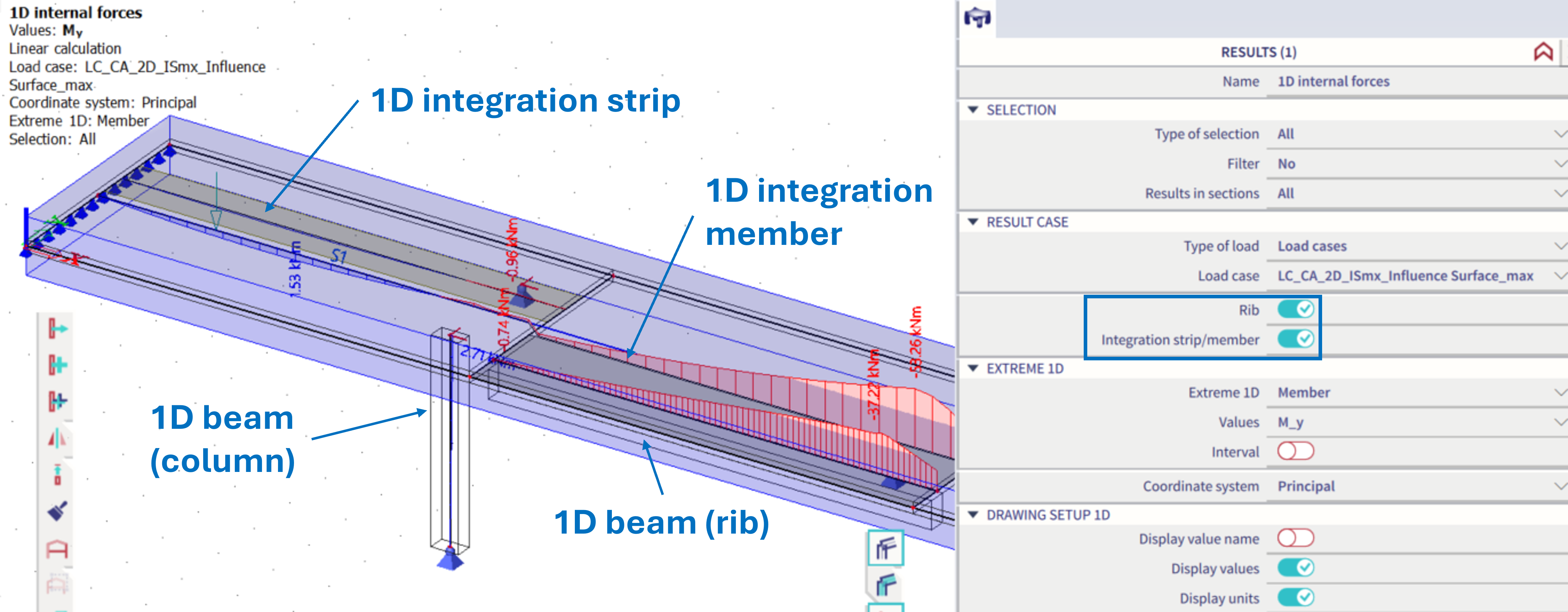
Also, for these generated load cases based on the influence lines, all the results are available, e.g. also 1D results on the corresponding 1D beams, ribs, or integration strips and members if applicable:
Summary of the options for 2D mobile loads
Options and features are summarized in the table below for the three possible work flows.
|
Settings within the moving load generator 2D
|
#B, Type of generated load cases = Envelope #G, Compute with influence lines = Off |
#B, Type of generated load cases = Envelope #G, Compute with influence lines = On |
#B, Type of generated load cases = Influence surfaces |
|
Is using influence lines / surfaces? |
No |
Yes, in the background, no need of special influence line / surface load cases to be defined by the user |
Yes, explicitly defined by the user, need to define special influence line / surface load cases manually |
|
Are the defined multipliers for the load in favourable and / or unfavourable direction considered? (see #H, #I in the chapter Load Systems 2D) |
No, because there are no influence surfaces, so the information where the load is acting in favour is unknown. |
Yes, there are influence surfaces, so the load might be altered based on these results. |
Yes, there are influence surfaces, so the load might be altered based on these results. |
|
Necessity to select 2D member components within the moving load generator 2D (see in #H,#I in this page) |
Yes, 2D internal forces and / or reactions (both #H,#I from this page) |
Yes, only 2D internal forces (only #H from this page) |
No, the member component is directly defined within the influence line / surface load case setting. |
|
Generated result load cases and their results |
Two; each is envelope type; not result for specific load position, but envelope of results for loads on all positions along the traffic lane 2D; one for maximal value of the result; second for the minimal value of the result. In these result load cases, either ONLY 2D results or ONLY reactions are present (according to selected component), not both. |
Two; each is envelope type; not result for specific load position, but envelope of results obtained from calculating numerous influence surfaces; one load case for maximal value of the result; second for the minimal value of the result. In these result load cases, ONLY 2D results are present (according to selected component) |
Yes, based on the influence surface, there are two result load cases, each load case works with one exact position of the load, these positions are just automatically generated based on the influence surface. All the results are present for each of these load cases (reactions and 2D internal forces together). |
|
Calculations in the background |
By brute force, many linear load cases with varying load positions respecting the step size are calculated, envelope results are provided |
By brute force, many influence surfaces respecting the defined step are calculated along the traffic lane 2D (in a way described in a cell to the right). It works as if the user defined many positions for influence surface along the traffic lane. For each such position as many influence surfaces will be calculated as many 2D member components are selected within the moving load generator 2D (see #H in this page). Only positions at the traffic lane are considered, no influence surfaces for reactions are considered in the background (it would need to iterate through all the nodal supports, but actually if there were any line or surface supports, these would be still avoided, providing partial result only) - due to this fact, there are no results for the reactions. |
Based on the user defined influence surface, the positions of considered load to yield maximal and minimal value of the selected component are determined. This is done by a numerical integration of the influence surface, respecting the step size from the setting. |
|
What does the Surface Loads (2D results) show? |
For each of two generated result load cases it shows the same result - just the first position of the load from all the possible positions that are considered in the background calculations |
For each of two generated result load cases it shows the same result - just the first position of the load from all the possible positions that are considered in the background calculations |
For each generated load case, it shows exactly what load on what position was considered. This load was automatically positioned to get the extreme effect of the selected component. |
|
Computation time |
Might take longer, as all the varying positions of the load are calculated by the brute force |
Might take longer, because there are many influence surfaces calculated in the background |
Slightly more time to manually define positions by the user, but then only explicitly defined load cases are calculated - based on specific project, might be the fastest of these 3 options |
|
Possibility to obtain the maximal effect of some component in a point outside the defined trajectory of the Traffic lane 2D (which is 1D line)? |
Yes, for each node of the structure the maximum and minimum result are provided |
No, the influence surfaces are calculated for the points along the traffic lane only |
Yes, just manually define the unit load (position for the influence surface) anywhere on the structure. |
|
Possibility to integrate the 2D internal forces from slabs to 1D internal force onto either ribs, integration strips or integration members? |
No, For the envelope result load cases, it is not possible to integrate the 2D results onto 1D results, keep this in mind when creating a combination containing these result load cases and some other load cases along with the integration members (strips or ribs) - the internal forces from these result load cases are NOT INCLUDED |
No, For the envelope result load cases, it is not possible to integrate the 2D results onto 1D results, keep this in mind when creating a combination containing these result load cases and some other load cases along with the integration members (strips or ribs) - the internal forces from these result load cases are NOT INCLUDED |
Yes, the 2D results are integrated into 1D by a standard ways, as these results from generated load cases are not envelop types. Ribs, integration strips and members work the standard way. |
|
Overall presence of 1D results |
No, these are only result load cases based on envelope, and ONLY the results for selected components are yielded (see #H,#I in this page) |
No, these are only result load cases based on envelope, and ONLY the results for selected components are yielded (see #H in this page) |
Yes, all the results are available |
|
Automation of the input? |
Yes, define the traffic lane and all the possible positions are considered |
Yes, define the traffic lane and all the possible positions are considered |
No, user needs to think what component and where to calculate, need to explicitly define. |
|
Conclusion |
Is automated, less manual work, does not use the multipliers based on favourable / unfavourable load position; provides also results for the reactions within the corresponding generated envelope load cases. Problematic usage of integration members (strips or ribs) - will not contain the 1D forces out of mobile load. |
Is automated, less manual work and enables using of the load multipliers based on favourable / unfavourable load position; but provide no results for the reactions at all. If results for the reactions are desired, these needs to be obtained by one of the other methods. Problematic usage of integration members (strips or ribs) - will not contain the 1D forces out of mobile load. |
Is the most robust, transparent, but requires the most manual work and user thinking; provides all the results, as the generated load cases are standard, not envelope type. No problems with the integration strips, members and ribs. |